Showing posts with label electronics. Show all posts

Thursday, August 28, 2008

On the bench - double sideband exciter

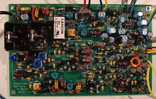
I recently constructed the Bitx20 kit and so far, despite willing help from the Yahoo! group, I've failed to get it working.

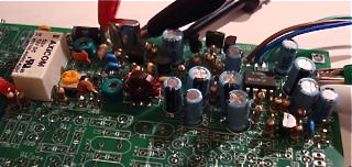
dsb.jpgIt's hard debugging a densly packed circuit board, so I decided to build a duplicate transmitter chain ugly style as you see here.

This is most instructive for me. It's laid out pretty much as the circuit diagram and I can easily measure at any point.

The Bitx20 is a marvellous design and there are lots of handy guides to construction and tuning around but, for me, what's missing is a circuit diagram with both DC and AC waveforms at every stage in both transmit and receive mode.

Anyhow, it's all for the best. I've often built a kit that's just worked first go and really it doesn't teach me anything. I'm hoping that after getting something similar going in this way I'll be able to go back and compare with the PCB version and figure out what's wrong.

Tuesday, August 19, 2008

Where are all the induction cookers?

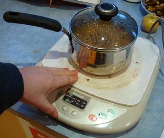
induction.jpgApart from a rice cooker, the other gadget we picked up during our stay in Hong Kong is an induction cooker.

You don't see them in stores in Australia for some reason.

Now that the big element on our electric stove top has died, again, I've brought it out of retirement.

Induction cookers work by inducing an electric current in the metal base of the pot that's sitting on it. This means that the heat generated in that metal is transmitted directly to the food being cooked rather than being partially lost in the kitchen. As you can see from the picture, the device itself remains cool.

In use, the induction cooker is very responsive and includes some advanced features for running a program of temperatures over time, but we never use those.

I read on Wikipedia that induction cookers are twice as efficient as electric elements or gas cookers, [although citations are needed].

The only downside is that it only works on pots with a thick, non-laminated base. If the pot isn't suitable the cooker sits and blinks until it feels something it can induce.

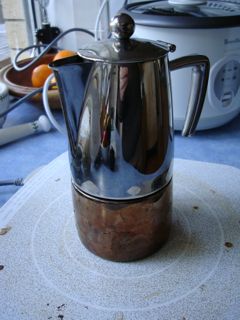
Works nicely with my coffee maker:

pot.jpg


I wonder why they aren't in the stores here?

Sunday, August 03, 2008

Building a BITX20 20m SSB transceiver

The current project on the bench is a single sideband transceiver for 14Mhz. It's a kit from Hendricks.

bitx20.jpg


I'm following the instructions and testing as I go rather than one big "smoke" test at the end. So far receive/transmit switching works, the audio amplifier and mic pre-amp and mixer work. Very encouraging.

I first heard about this design on the Soldersmoke podcast. It's by Ashhar Farhan VU2ESE, his article is here.

There is much to commend this circuit, coming out of India it is designed to use low cost easily obtained components. Ashhar comments that if you can't get (or afford) torroid transformer cores, tap washers may be substituted.

amp.gifThe circuit is "bi-directional" in that it uses the narrow crystal filter for both receive and transmit and switches amplifier stages using diode switches. The amplifier stage is pretty much the same throughout so despite the switching it's pretty easy to see how it works.

The kit I'm constructing is revision 3 and has push pull IRF510s in the output so it should deliver about 10 watts which is quite substantial with a reasonable antenna on 20m.

I plan to build this into a box including the frequency counter from Doug N3ZI mentioned earlier.

Update

Construction is going well although I found a few missing and substituted components in the kit.

bitxcomplete.jpg

I'm looking for a signal on 20m to use for receive alignment.

Friday, July 25, 2008

Low cost embedable frequency counter

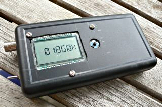
Frequency Counter.jpgHeard about this on the wonderful Soldersmoke blog. A flexible digital display for home home brew radios, from Doug N3ZI.

The pre-scaler is configurable to make it useful in ranges up to 50Mhz or so. It uses an Atmel ATtiny24 which comes pre-programmed. The software includes clever things like handling the IF offset.

Normally, low cost frequency counters tend to show annoying jitter in the last digit but the author has overcome this so it seems very stable in operation.

There are three versions of the kit, from $10 to $30 for the full kit. I bought the full kit and it came quickly, went together easily, and worked first time.

I'm thinking of pairing it with a Bitx20.

Thanks Doug!

Update

I've hooked it up to an MMR40 7Mhz rig.

MMR40 counter.jpg


I needed to make a buffer amplifier to boost the local oscillator level enough for the counter. It's based on a snippet from Experimental Methods in RF Design.

rf amplifier.png


The local oscillator output is 0.27V peak to peak, after the transistor buffer it's 1V peak to peak. I used a 2N2222a that I had on hand.

The counter was set to an IF offset of -10Mhz. Doug's software lets you do this with ease using up and down buttons that accelerate if you hold them down.

There's a plastic box HB5970 that fits pretty much perfectly. It's 140 x 110 x 35mm the CPU board slides into slots and I've just used the LCD board as the front panel (a bit ugly but functional).

box content.jpg


Having boxed it all up it looks great:

front working.jpg


I had to increase the input capacitor's value in the counter to get it to be sensitive enough with my buffer to work reliably.

Anyhow, a great kit. Highly recommended.

Sunday, May 11, 2008

Controlling an AD9851 with an Atmel AtTiny85 (or other)

avrdds.jpgFollowing on from my last post, I got something similar working with an ATTiny85. This sample code does a slow sweep from 10Mhz up a bit. It's just a demo, the bit I've been looking for myself and couldn't find was how to just say sendFrequency().

I have lots of ideas for applications of these things, including:


  • General purpose VFO with keypad and knob

  • Sweep test generator, paired with a digital rf signal measurer for computer plotting filters etc

  • Automated antenna analyser with a digital SWR measuring thingy


This code is written in C and uses avrlibc. I'm working on a Mac but it will work the same on Linux or that other OS that was quite popular.


/*
Control an AD9851 DDS with an ATMega85
*/

#include <avr/io.h>
// Sets up the default speed for delay.h
#define F_CPU 800000UL
#include <util/delay.h>
#include <math.h> // for pow()

// Pins used to talk to the DDS chip
#define LOAD 4
#define CLOCK 3
#define DATA 0
#define LED 1

#define DDS_CLOCK 180000000UL

#define OUTPORT PORTB
#define OUTPORTDIRECTION DDRB

void sendFrequency(unsigned long frequency);
void byte_out(unsigned char byte);
void outOne();
void outZero();
void bitSetHi(volatile uint8_t *port, int bit);
void bitSetLo(volatile uint8_t *port, int bit);

int main (void)
{
OUTPORTDIRECTION = _BV(LOAD) | _BV(CLOCK) | _BV(DATA) | _BV(LED);
unsigned long freq;

// flash an led to show we're alive
int i;
for(i = 0; i < 10; i++)
{
bitSetHi(&OUTPORT, LED);
_delay_ms(100);
bitSetLo(&OUTPORT, LED);
_delay_ms(100);
}
while (1)
{
// Do a frequency sweep in Hz
for(freq = 10000000; freq < 10001000; freq++)
{
sendFrequency(freq);
_delay_ms(1);
}
}
return 0;
}

void bitSetHi(volatile uint8_t *port, int bit)
{
*port |= ( 1<<bit );
}

void bitSetLo(volatile uint8_t *port, int bit)
{
*port &= ~( 1<<bit );
}

void sendFrequency(unsigned long frequency)
{
unsigned long tuning_word = (frequency * pow(2, 32)) / DDS_CLOCK;
bitSetLo(&OUTPORT, LOAD); // take load pin low
int i;

for(i = 0; i < 32; i++)
{
if ((tuning_word & 1) == 1)
outOne();
else
outZero();
tuning_word = tuning_word >> 1;
}
byte_out(0x09);

bitSetHi(&OUTPORT, LOAD); // Take load pin high again
}

void byte_out(unsigned char byte)
{
int i;

for (i = 0; i < 8; i++)
{
if ((byte & 1) == 1)
outOne();
else
outZero();
byte = byte >> 1;
}
}

void outOne()
{
bitSetLo(&OUTPORT, CLOCK);
_delay_ms(1);
bitSetHi(&OUTPORT, DATA);
_delay_ms(1);
bitSetHi(&OUTPORT, CLOCK);
_delay_ms(1);
bitSetLo(&OUTPORT, DATA);
_delay_ms(1);
}

void outZero()
{
bitSetLo(&OUTPORT, CLOCK);
_delay_ms(1);
bitSetLo(&OUTPORT, DATA);
_delay_ms(1);
bitSetHi(&OUTPORT, CLOCK);
_delay_ms(1);
}


The AMQRP board has it's own regulator and has a 5V output so I'm powering the ATTiny85 from that power rather than a separate input. Here's a nifty spot reference. Simple enough even for me to build.

spotGen.jpg

Wednesday, March 26, 2008

Harvesting parts from an inkjet printer

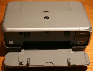
external.jpgEver since I attended a workshop on stepper motors at Dural conducted by Peter VK2EMU I've been watching for the site of an inkjet printer by the side of the road and this morning there was a rather wet Canon calling me...

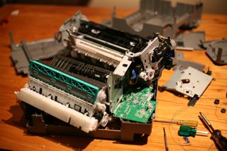
After about half an hour of messing about the device was a wreck but these printers sure are a treasure trove of useful parts for the home robot maker: cogs, rollers, pulleys, switches, sensors and motors. Regrettably, this model doesn't use stepper motors but rather they seem to be DC motors with a rotary encoder linked to each one.wreck.jpg

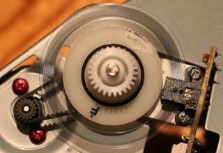
The encoder disk is amazingly fine and it passes through an optical reader which I guess is rather like the encoder in a mouse. The markings are 7120 G516 but so far I haven't found a data sheet for them. The board has 4 wires coming from it so there's not too many options.encoder.jpg

Anyhow, despite my disappointment about the lack of steppers, I did score four very nice DC motors that seem to run well on about 3 volts and will be suitable for computer control or making little robots like this.parts.jpg

It's truly amazing the amount of perfectly good electronics that are available for free at council junk collection times.

Thursday, March 20, 2008

Got AD9851 Direct Digital Synthesiser working.

There's a lot of interest in ham radio circles around the new DDS chips which can act as a high stability VFO over a wide range with very fine control.

DDS CRO.jpgAfter hearing about them at a NSW Home Brew meeting, I purchased an AD9851 on eBay and have had about a week of frustration trying to program the thing. You need to send them a clocked 40 bit sequence to set the frequency.

I have been playing with a variety of Atmel AVR processors on various boards and in the end I found some wonderful software for the AVR Butterfly board by Stephen Weber, KD1JV, which has several versions including one for a transceiver and another for a straight VFO. (I'm using the VFO version). Programming was via an AVR ISP MkII rather than the serial protocol, I'm sure either would be fine.

The AVR Butterfly board includes a display and a 4 way rocker switch (plus push) that is used to control the frequency.

DDS Display.jpgNext steps are to put this in a nice box with more robust buttons, output filtering and amplifier. In summary, this gives the builder a very flexible oscillator for not many dollars. It's certain to become a core part of many future radios coming out of the Marxy lab in the future.

So, thanks so much to KD1JV for his excellent software, supplied with source, that has got me started and thanks to members of the NSW Home Brew group including John VK2ASU for his encouragement and offer of a chip in case I'd "smoked" mine.

An AVR Butterfly is about US$20 (a bargain) and I paid AU$50 for the AD9851 plus 30Mhz oscillator and a carrier board, which I consider pretty good all up.

DDS in box.jpgI've put this prototype in a little box to serve as a portable digital signal generator. Tried to run it off two AA batteries but the voltage was a little low for the 30Mhz oscillator to work reliably. (The AVR Butterfly is perfectly happy at low voltage though).

Saturday, February 09, 2008

Built a better PSK31 interface box

pskVoxInterface.jpgStarted playing with PSK31 on my mac last year as reported earlier. As I said, I'm running the excellent CocoaModem software.

Until last week I was using the RTS line on a USB serial cable to key the transmitter which made for rather too many cables on my desk so I've jumped in and built a better interface box that has a VOX for keying PTT and includes level controls for both send and receive audio.

The box includes my old audio interface with 600/600 ohm transformers for audio in and out and ads a VOX board I built from a jaycar kit. Initially I ran in to some RF effects that caused the PTT relay to drop out during transmit, but the addition of RF chokes on all inputs and some bypass capacitors seems to have cleared up the problems.

On the back is a 5 pin DIN plug so I can make leads to connect to my rigs. To start I've made an Icom data cable.

So far I've had contacts with New Zealand and Queensland and can hear people in WA, SA and Victoria. We've had a lot of rain recently and I'm not sure that my home constructed balun has kept out the water. (The TV used to black out when I transmitted and it isn't any more - so in my book that's a bad sign...).

Very much hoping to catch up with VK3SL, Les, in Melbourne if he gets set up.

Wednesday, January 02, 2008

Getting started with Atmel ATMEGA8-16

I mentioned in a previous post that I've been interested in learning about the Atmel AVR microcontrollers.

To get started I purchased an already constructed Arduino board and had a good experience using it's USB/Serial programming from my Mac.

I don't feel satisfied until a controller board has been built from components, here's what I did.
  • Purchased an ATMEGA8-16 from the local Jaycar for AU$19.95
  • Built a minimal circuit based on the Arduino but without the USB stuff.
    • I kept the power LED and bypass capacitors but that's all
  • Built a simple PC Parallel port programmer based on this circuit (yes, just two resistors!)
  • On a Fedora 8 machine, did "yum install avr-gcc avr-libc avrdude"
  • Add your user to /etc/groups under the lp group so you can access the parallel port
  • I followed the excellent instructions by The Real Elliot here to get a sample program going and make a Makefile.
One thing that caught me for a while is that while plugged in to the programmer, the chip doesn't run. I'm sure I can fix that by adjusting the reset line or something.

I've also changed the fuses on a chip so that I now get "avrdude: AVR device not responding", still trying to figure out how to get out of that issue.. All good fun.

Wednesday, December 26, 2007

Variable DC regulator V1

I'm getting really sick of those little "wall wart" power bricks for everything. My collection is getting silly, particularly as the multi-voltage ones seem to never quite have all the voltages I want.

My recent purchase of an Asus EEE PC is a good case in point, I imported it from Hong Kong so it has a power brick with a dodgy mains adapter plug on the back of it. This device needs 9.5V DC to charge - none of my existing adapters will provide this - hence this week's mini project.

It's a classic LM317 variable DC regulator in a box with a knob. The circuit is straight from the data sheet here. In my version I have 100R for r1 and the potentiometer is 1K. On the input I have a bridge rectifier so I can plug either polarity in to it without fear. Construction is on a tag board, probably a heatsink and some ventilation holes will be needed but the LM317 is well protected against over temperature and current problems.

I'm calling this project version 1 as it turns out it can't supply the 2.3A needed to charge the EEE PC, still useful for other things, but a version 2 is going to be needed for my original objective. Looks like I need an LM150 or LM138 for that.

Thursday, December 20, 2007

Arduino controller board on a Mac

Having played with PIC microprocessors for many years and had good times with the 16f628, it's been hard for me to jettison that knowledge and move to another chip even though it looks much better.

The Atmel AVR chips are low cost but designed for running code generated by "normal" compilers like good old gcc, rather than the PIC chips that need hacked c or basic compilers that know how to use that banked memory.

I use a Mac and always feel like a second class citizen when it comes to software and hardware for embedded systems. Make magazine featured a little board called Arduino that carries an ATMega168 chip.

It's the fastest "greet postie" to "das blinken lights" joy I've ever experienced.

Here's my list of observations so far:
  • The Arduino is open source so you can make your own
  • I bought the Diecimila for AU$37.50 with it's USB connection
  • Chip programmed with a boot loader so it is re-programmed via serial (over USB)
    • The boot loader is freely available so you can burn it into your own chips
  • There is an IDE for Windows, Linux and the Mac that works really well
  • The IDE for Mac comes with the driver you need for the USB interface
  • IDE has gcc-avr built in
    • It links against AVR Libc
    • Language is most of c
    • Syntax colouring
    • Seems actually to use a c++ compiler
    • Has some useful built in functions for doing i/o
    • Comes with libraries for things like printing to serial (and you can do serial comms to the board in the IDE so that's how you debug)
    • There are third party libraries available for stuff like digital servo control
    • Libraries are installed by simply dragging them in to a folder
  • The board can be powered by USB or a separate supply 6-12V
  • When you compile your source the output, including the intel hex file is dropped into a folder with the source so you can even burn it to another chip with your own programmer
What held me back from trying the Atmel AVR chips is the fact that there's so many of them! Where to start? Well, it seems like the ATMega8 is a good start. All the tools are free and if you have a PC with a parallel port you can make a really simple programmer.

Incidentally, I ordered my Arduino from Little Bird Electronics here in NSW on 9-December and it only turned up today 20-December. I think that's a little slow.

Wednesday, November 28, 2007

Chu Moy Headphone amp PCB design

I've built a number of Chu Moy design headphone amplifiers over recent months and recommend them so highly to friends I end up giving them away. Previously written up here.

Ugly construction is fine for one or two off, but it was time to try manufacturing a printed circuit board.

When I last made a printed circuit board, it was done photographically, by exposing a chemical resist to ultra violet light. Having just dismantled my dark room, it was time to try a different technique.

I used some blue "press-n-peel" transfer film. The design was done manually in OmniGraffle, printed on the film with a little HP laser printer, ironed on to the board on a wool setting, etched and drilled all in a couple of hours.

This technique works pretty well, I've had a little trouble with the ironing phase, the transfer moves a bit when I iron it on. On one occasion I had to rub off the bad transfer and iron on again. The instructions say to set the iron to polyester, but our iron doesn't have it so I set it to wool.

The actual circuit for this board uses two OPA134 amp chips (rather than the dual chip) and a TLE2426 rail splitter. I don't include any volume control as the device driving it, generally a computer or digital player has one.

I present here revision 2 of a PCB design. It works but could be more compact and has two links. PDF here, OmniGraffle source here. Note that the writing will be mirrored on the copper side when you make it. (I haven't figured out how to mirror text in OmniGraffle..) 

You are free to use these for any purpose. (Let me know if you improve it).

Be careful that your printer is close enough to 100%, I suggest test printing and lining up the 8 pin IC which is the only critical spacing.

Monday, July 30, 2007

Free stepper motors

Another entertaining meeting of the Amateur Radio New South Wales Homebrew Group on Sunday at Dural. Peter O'Connell VK2EMU presented an introduction to the use of stepper motors.

He explained how they work, (by stepping normally 200 little steps per revolution), how they are wired (4 wire, 5 wire, 6 wire arrangements), and how to drive them with a few darlington transistors and a PC parallel port.

It will be a great loss when no computers are available with parallel ports any more but I guess the wide availability of USB chipsets will help here.

A few interesting projects were discussed such as a plotter that can directly cut the copper on a circuit board to make printed circuit boards without etching, and home built milling machines for manufacturing.

The great thing about stepper motors is that they are one piece of precision equipment that can be obtained free. All of those ink jet and laser printers that get left out on the curb during council junk collections contain one.

Show and Tell was great too, Graham VK2GRA showed how he was using electric fence insulators for dipole construction, Stephen showed off his excellent 80m AM challenge transmitter, and Alan VK2ZAY had built a 2M AM transceiver in an Altoids tin plus a fantastic tiny short wave receiver.

Tuesday, June 12, 2007

Contributed an item to SolderSmoke

I've been going to the NSW Home Brew group recently and last meeting I took a digital recorder along and spoke to some of the members about what they were up to. I thought it might be of interest to the SolderSmoke podcast and, indeed, it was.

Bill was very encouraging and has run the item in podcast number 62. His intro starts at 19mins 45 seconds in to the program (but listen to the whole thing).

Thanks to Bill for including the item, sorry about the roudy background noise, and thanks of course for the members who agreed to be interviewed. It was tough chopping down to ten minutes, I have enough good material for two more spots still in the can.

Saturday, May 26, 2007

Built a 40m SSB transceiver kit: MMR-40

Since having a wisdom tooth out on Tuesday I've been laying low this week and took the opportunity to construct a kit.

Shown at right during construction, the MMR-40 from Hendricks QRP kits is a great little kit transceiver. Mine was missing a couple of diodes but was otherwise complete. I had a few problems getting the receiver going due to the fact that I hadn't read the errata and mistook the different zener diode for one of the missing diodes and experienced some very strange voltages that affected the transmit/receive switching circuit.

After a long night of hair pulling I joined the Yahoo MMR40 owners group and posted a question about my symptoms. Very quickly Tom replied from a Blackberry with a pointer to the problem. Great stuff.

I find building kits is a great way to get familiar with components and in particular diagnosing problems helps me greatly in understanding the circuit. I never dreamed that I could build an SSB transmitter. Still some work to do to get it all lined up but it seems to be putting out a few watts.

An interesting part of this design is the permeability tuned oscillator where part of the inductance is varied by screwing a brass bolt in and out of the coil. You can see it at the bottom right of the image above. Counter-intuitively, to me, is that frequency goes down as you wind the bolt in. The good thing is that you get slow change over turns of the knob and it seems remarkably unaffected by hand capacitance.

Update: After swapping out the mis-placed zener the receiver was still a little disappointing. Turned out that like others I had followed the layout diagram and installed a 22pF capacitor at C18 which caused T1 not to tune up. The only other oddity is that if I turn my variable supply up much above 12V the receiver mutes, not a big deal.

Anyhow, the receiver is working really nicely and is sensitive enough to hear all that bad band noise on 40m, which is all you need really. I'm not confident that my transmitted SSB is right yet, it puts out power when I talk but doesn't look like real SSB just yet.

A simple modification has been to install a stereo headphone jack that cuts off the speaker. Builders should note that the speaker really comes to life when you put it in the box and close it, very soft on the bench on its own.

I'm enjoying this but I think the kit errata needs an update. The design is very clever in that it re-uses lots of components for both receive and transmit but it lacks a block diagram so I've tried to create my own here.


(Click for a larger version). Please send me corrections!

Incidentally, wisdom tooth removal went very well - the wonders of modern dentistry.

Sunday, May 13, 2007

Progress on the 80m challenge transmitter

Finally making progress on the NSW Home Brew group's 80m challenge project to build a 20W 80m AM transmitter.

I'm a bit daunted as I have never made anything that puts out more than about 500mW and have very little RF experience, but progress is finally being made.

A design has been cobbled together based on the Hendricks QRP TwoFer design, built for 80m.

So far I have the oscillator and a buffer stage running nicely and I'm looking for an RF power transistor to get to 2W. I can't seem to source a 2N2553 or 2SC799 so I've ordered from the U.S. but disappointingly they say it won't ship for up to 3 weeks.

The smoke from an MPF102 was released along the way due to wiring it in reverse.

In other news, I picked up 20m of RG213U co-ax from the MWRS at a great price. I've run this through a hole, up between the double brick walls, through the ceiling and to my newly stretched out 40/80m dipole upstairs.

Reception is great but when I transmit all hell breaks loose from RF getting into audio amplifiers. Once again, my long wire antenna looks like being the most practical transmitting system here.

Sunday, April 29, 2007

Organizing electronic components

I had a plastic box full of resistors collected over the years. When building some project, one of the hardest things for me is finding the right components in that jumbled mass. In the past I've tried tackle boxes with lots of drawers, but there's never enough for all the different resistors and they often need their leads bent to fit.

Found a great thread on slashdot on this topic where someone suggests this method.

I bought a bunch of 15cm x 9cm snaplock bags and a box that fits them nicely. Spent some time sorting out the collection (only resistors done so far, capacitors are next).

The plastic bags have a nice place to write the values on them and all. This system is very compact and if you get a value to file that fits between two others it can be simply inserted without the need to move all the drawers.

The point has been made that this probably isn't a good idea for static-sensitive components, but I just thought I'd put them in the bag inside their anti-static bag or foam pad.

No doubt this whole exercise is really just elaborate procrastination.

Thursday, April 26, 2007

Home work space

This is a response to Alastair's excellent workspace post. My little home office is a mess. I have three main hobbies: photography, computers and ham radio. They all compete for space at home.

Regrettably I don't have a nice window to look out of at a calming garden so I've added a second screen to give me a wider panorama.

From left to right: A monitor supported by books I try to keep in my unconscious. Above, on the wall, a print from the master (well from his 8x10 negative). An Intel iMac. Altoids I'm munching to make way for electronics projects. iPod loading up with too many podcasts to get through. (I've recently ditched Scoble and Calacanis as they make too much).

On the right, below puzzled daughter Catherine, is my radio hobby. An MFJ-902 travel tuner (excellent), an FT-817 I had a great time with while camping, an old Emtron tuner that I only learned how to use from the instructions that came with the MFJ tuner, a receive only tuner just being used to hold things up, and finally my boxed DRM receiver.

The transceiver is tuned to 80m via a long co-ax run through the wall, then ceiling and out to the top floor to a very narrow trap 40m and 80m dipole. Lots of activity these days on HF.

Friday, April 06, 2007

Built a tiny 80m AM transmitter

I've been attending the Amateur Radio New South Wales Homebrew Group meetings recently, both on air and in the flesh.

Most entertaining. This year they have a "challenge" (not a competition!) to build an 80m AM 20W transmitter. I haven't done any electronic construction for years and haven't really attempted RF projects.

To warm up for this challenge, I've just completed a tiny 80m AM transmitter based on a circuit found here.

This is my second attempt, the first time around, I tried to build it from the limited parts I had around. If the circuit said 5k1, I'd use 4k7, and so on. Anyhow, it didn't work so I went and bought the right bits and now it does work. The only substitution is that I used 2N2222a transistors in place of 2N4401s.

This is also my second project using the "Manhattan Pad" technique which I'm very comfortable with now.

Monday, March 26, 2007

Apple TV arrived in Sydney

My Apple TV just arrived here in Sydney.

Not much I can say so far except the box is pretty nice. It shipped on the 20th and just arrived now, a bit longer than expected.

Later: Now that I've got it going, here's my impressions:
  • Very easy to set up, booted, on the network, shows a number that you key into the iTunes you want to pair it with.
  • By default it started syncing all my Music. I didn't buy this thing to play music on the TV so I've changed that default.
  • iTunes immediately tried to sell me music videos, which is about all there is in Australia at the moment, I fell for it and bought a few clips.
  • The TV trailers are tantalising, Lost, Grey's Anatomy, etc etc. Of course we can't buy any of these in Australia. Grrr...
  • The interface lags a little but probably because it was madly trying to sync my music library.
  • Visually, looks lovely.
We don't have cable TV and I'm prepared, keen in fact, to spend the money that would have gone on cable, on purchasing shows I really want to see.

Issues:
  • It doesn't play everything I can play in iTunes. Not sure why, I've got a quicktime movie in my library that won't sync over.
  • Some videos, including movie trailers from Apple lose their Video/Audio sync pretty badly.
  • iTunes kind of forgot about my iPod for a while. Had to re-boot the iPod, seems ok now.
  • They need a black version, after all, most flat screen TVs come in black.
  • Why doesn't the volume control work? The nifty remote control only has 6 buttons and two of the don't do anything.
I'm happy with the product and very much enjoyed watching video podcasts in bed last night. Can't wait to buy a TV show or movie.