Showing posts with label home brew. Show all posts

Saturday, July 26, 2008

GutterTool Pro Turbo (with clearvu leaf mirror)!

GuttMaster.jpgThe gutters here at Marxy Manor are full of leaves and when it rains they overflow in all the wrong places.

Being a fan of PVC pipe constructions (see the laptop stand) I had a bright idea that a quick trip to the "$2.50" shop provided the bits for.

To be honest, it doesn't work too well, the mirror goes out of alignment very quickly and the force required to lift the twigs and leaves it too much for the flexible pipe I'm using - perhaps pressure pipe is the answer.

GuttMasterView.jpg


Anyhow, a bit of home invention is great fun. Could this be the next "stump jump plough"?

Friday, July 25, 2008

Low cost embedable frequency counter

Frequency Counter.jpg
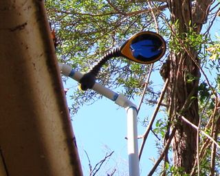
Heard about this on the wonderful Soldersmoke blog. A flexible digital display for home home brew radios, from Doug N3ZI.

The pre-scaler is configurable to make it useful in ranges up to 50Mhz or so. It uses an Atmel ATtiny24 which comes pre-programmed. The software includes clever things like handling the IF offset.

Normally, low cost frequency counters tend to show annoying jitter in the last digit but the author has overcome this so it seems very stable in operation.

There are three versions of the kit, from $10 to $30 for the full kit. I bought the full kit and it came quickly, went together easily, and worked first time.

I'm thinking of pairing it with a Bitx20.

Thanks Doug!

Update

I've hooked it up to an MMR40 7Mhz rig.

MMR40 counter.jpg


I needed to make a buffer amplifier to boost the local oscillator level enough for the counter. It's based on a snippet from Experimental Methods in RF Design.

rf amplifier.png


The local oscillator output is 0.27V peak to peak, after the transistor buffer it's 1V peak to peak. I used a 2N2222a that I had on hand.

The counter was set to an IF offset of -10Mhz. Doug's software lets you do this with ease using up and down buttons that accelerate if you hold them down.

There's a plastic box HB5970 that fits pretty much perfectly. It's 140 x 110 x 35mm the CPU board slides into slots and I've just used the LCD board as the front panel (a bit ugly but functional).

box content.jpg


Having boxed it all up it looks great:

front working.jpg


I had to increase the input capacitor's value in the counter to get it to be sensitive enough with my buffer to work reliably.

Anyhow, a great kit. Highly recommended.

Sunday, June 15, 2008

Building a software defined radio

softrockfront.jpgI'm building the new Softrock "Xtall+Lite" v8.3 from Tony Parks KB9YIG.

He definitely needs to come up with a snappier name!

All seems well on the receiver front although it doesn't seem very sensitive and I suspect my front end isn't resonant in the right place. Shown above is the 40/80m front end.

Construction went well and all seems to check out ok. This board has a few surface mount components that take me a bit of concentration. The little DIP switches set the oscillator frequency.

First I had a go with Linrad on a Linux box but I seem to have sound troubles, so over to the Mac. My frustration is trying to get some SDR software running on the Mac. I spent several hours trying to get UWSDR to build on Leopard, after fixing all the little type casting complaints it wouldn't link with libfftw (missing symbols) so I'm stuck for now.
softrockback.jpg

In other news, I finally heard some PSK31 stations on 80m, VK2BOJ and VK2DD were heard on about 3.660Mhz with excellent signals. We were on our way out the door but I transmitted a few Hz away and they noticed and said hello. I only had time to say I had to go but this is a good sign.

It puzzles me why people give reports such as "599" when using PSK31, surely "S9 and -23db IMD" would be a more useful measure.

Update: I've just been pointed to some SDR software for the Mac by Sebastian DO8SEM here. Looks very promising although still under development. Currently, I'm not hearing too much but it has great promise.

Here it is on 80m. The audio seems rather distorted to me but it certainly works and I'm happily listening to SSB conversations.

SDRTransceiver.png

Tuning shortwave with a "waterfall" display is certainly the best way to operate.

Update 2:I figured out why my softrock was so deaf, the tuned RF front end is supposed to provide anti-phase signals at the input but in my case I had the phase of one side reversed. Works much better now.

Sunday, June 08, 2008

Had a contact with a $5 80m DSB radio

80mDSB.jpgStephen, VK2BLQ, has been selling off his old projects and I picked up an 80m double sideband radio he built for $5.

The only modification I've made is to re-wire the microphone socket to suit the mic I have.

I ran into local ham, Rob, VK2ZNZ in the supermarket today and asked if he would listen out for a weak signal on 80m. We liaised by phone and without trouble he was able to find me and we had a fine chat with the radio. His only complaint was a slow drift in frequency but the audio was good both ways.

This design is one that was published in Silicon Chip in November 1994 and available as a Jaycar kit. A pity they don't offer anything like that now. It's 1.5W PEP out and Rob said I was a little noisy but perfect copy.

Thanks Stephen for the fine radio to play with. Thanks Rob for helping me out.

Sunday, May 11, 2008

Controlling an AD9851 with an Atmel AtTiny85 (or other)

avrdds.jpgFollowing on from my last post, I got something similar working with an ATTiny85. This sample code does a slow sweep from 10Mhz up a bit. It's just a demo, the bit I've been looking for myself and couldn't find was how to just say sendFrequency().

I have lots of ideas for applications of these things, including:


  • General purpose VFO with keypad and knob

  • Sweep test generator, paired with a digital rf signal measurer for computer plotting filters etc

  • Automated antenna analyser with a digital SWR measuring thingy


This code is written in C and uses avrlibc. I'm working on a Mac but it will work the same on Linux or that other OS that was quite popular.


/*
Control an AD9851 DDS with an ATMega85
*/

#include <avr/io.h>
// Sets up the default speed for delay.h
#define F_CPU 800000UL
#include <util/delay.h>
#include <math.h> // for pow()

// Pins used to talk to the DDS chip
#define LOAD 4
#define CLOCK 3
#define DATA 0
#define LED 1

#define DDS_CLOCK 180000000UL

#define OUTPORT PORTB
#define OUTPORTDIRECTION DDRB

void sendFrequency(unsigned long frequency);
void byte_out(unsigned char byte);
void outOne();
void outZero();
void bitSetHi(volatile uint8_t *port, int bit);
void bitSetLo(volatile uint8_t *port, int bit);

int main (void)
{
OUTPORTDIRECTION = _BV(LOAD) | _BV(CLOCK) | _BV(DATA) | _BV(LED);
unsigned long freq;

// flash an led to show we're alive
int i;
for(i = 0; i < 10; i++)
{
bitSetHi(&OUTPORT, LED);
_delay_ms(100);
bitSetLo(&OUTPORT, LED);
_delay_ms(100);
}
while (1)
{
// Do a frequency sweep in Hz
for(freq = 10000000; freq < 10001000; freq++)
{
sendFrequency(freq);
_delay_ms(1);
}
}
return 0;
}

void bitSetHi(volatile uint8_t *port, int bit)
{
*port |= ( 1<<bit );
}

void bitSetLo(volatile uint8_t *port, int bit)
{
*port &= ~( 1<<bit );
}

void sendFrequency(unsigned long frequency)
{
unsigned long tuning_word = (frequency * pow(2, 32)) / DDS_CLOCK;
bitSetLo(&OUTPORT, LOAD); // take load pin low
int i;

for(i = 0; i < 32; i++)
{
if ((tuning_word & 1) == 1)
outOne();
else
outZero();
tuning_word = tuning_word >> 1;
}
byte_out(0x09);

bitSetHi(&OUTPORT, LOAD); // Take load pin high again
}

void byte_out(unsigned char byte)
{
int i;

for (i = 0; i < 8; i++)
{
if ((byte & 1) == 1)
outOne();
else
outZero();
byte = byte >> 1;
}
}

void outOne()
{
bitSetLo(&OUTPORT, CLOCK);
_delay_ms(1);
bitSetHi(&OUTPORT, DATA);
_delay_ms(1);
bitSetHi(&OUTPORT, CLOCK);
_delay_ms(1);
bitSetLo(&OUTPORT, DATA);
_delay_ms(1);
}

void outZero()
{
bitSetLo(&OUTPORT, CLOCK);
_delay_ms(1);
bitSetLo(&OUTPORT, DATA);
_delay_ms(1);
bitSetHi(&OUTPORT, CLOCK);
_delay_ms(1);
}


The AMQRP board has it's own regulator and has a 5V output so I'm powering the ATTiny85 from that power rather than a separate input. Here's a nifty spot reference. Simple enough even for me to build.

spotGen.jpg

Saturday, May 10, 2008

Controlling an AD9851 DDS with an Arduino

ad9851.jpgBeen playing with the AD9851 DDS for a while now using other people's software mostly written in assembly language that I find rather hard to get my head around. Finally tonight, with the help of several others who have published their work on the internet I have got some simple code to drive this chip the way I want.

This can tell it the frequency the generate in Hz and it just works.

This minimal example does a small sweep from 10Mhz so it's easy to listen to on a radio.

While I prefer to use the atmel chips "naked" I do find the Arduino board a very convenient way to muck around and get things going in an interactive environment. This code doesn't rely on any magic Arduino libraries so it should be easy to port, I'll post a straight ATMEGA version soon.

The code presented here shows some things I've struggled to figure out: how to calculate the tuning word from the frequency and how to send the serial commands to the chip. I hope this helps someone else.


// Control a AD9851 DDS based on the good work of others including:
// Mike Bowthorpe, http://www.ladyada.net/rant/2007/02/cotw-ltc6903/ and
// http://www.geocities.com/leon_heller/dds.html
// This code by Peter Marks http://marxy.org

#define DDS_CLOCK 180000000

byte LOAD = 8;
byte CLOCK = 9;
byte DATA = 10;
byte LED = 13;

void setup()
{
pinMode (DATA, OUTPUT); // sets pin 10 as OUPUT
pinMode (CLOCK, OUTPUT); // sets pin 9 as OUTPUT
pinMode (LOAD, OUTPUT); // sets pin 8 as OUTPUT
pinMode (LED, OUTPUT);
}

void loop()
{
// Do a frequency sweep in Hz
for(unsigned long freq = 10000000; freq < 10001000; freq++)
{
sendFrequency(freq);
delay(2);
}
}

void sendFrequency(unsigned long frequency)
{
unsigned long tuning_word = (frequency * pow(2, 32)) / DDS_CLOCK;
digitalWrite (LOAD, LOW); // take load pin low

for(int i = 0; i < 32; i++)
{
if ((tuning_word & 1) == 1)
outOne();
else
outZero();
tuning_word = tuning_word >> 1;
}
byte_out(0x09);

digitalWrite (LOAD, HIGH); // Take load pin high again
}

void byte_out(unsigned char byte)
{
int i;

for (i = 0; i < 8; i++)
{
if ((byte & 1) == 1)
outOne();
else
outZero();
byte = byte >> 1;
}
}

void outOne()
{
digitalWrite(CLOCK, LOW);
digitalWrite(DATA, HIGH);
digitalWrite(CLOCK, HIGH);
digitalWrite(DATA, LOW);
}

void outZero()
{
digitalWrite(CLOCK, LOW);
digitalWrite(DATA, LOW);
digitalWrite(CLOCK, HIGH);
}


The board I'm using is the excellent carrier from AmQRP.

Sunday, May 04, 2008

Rough guide to surface mount soldering

smd.jpgI share an interest in good quality headphone audio with many including Alastair who purchased the board and parts for the Alien DAC. Not being too confident with the soldering iron he made a deal, he bought two sets, one for him and one for me, if I'd help him construct his one.

Surface mount components are either tiny themselves, like the resistors and capacitors, or if large, they have pins that are very close together and hard to avoid having the solder bridge between them. The move to computer manufacturing with surface mount components is unfortunate for us home constructors. Some parts are only available in surface mount packaging and I fear for the future of this fine past time.

I got both boards going and thought I'd share my tips on construction, which you can see from the image are not too good, but serviceable.

For the chips with many pins, hold down the chip with the point of angle ended needle nosed pliers (the weight of the tool will hold it in place - hands shake too much), tack solder one corner pin and one on the opposite corner, then remove the pliers. Just flow solder across all the pins on each side, then go back with fine solder wick and suck back all the excess solder.

For resistors and capacitors again use the point of angle ended needle nosed pliers to hold them in place while soldering one end.

I think I'll put my new audio output device in a nice box along side a powered amplifier as covered in the past. Thanks Alastiar for the bag of bits!

Sunday, April 27, 2008

Clothesline style antenna hoist for experiments

AntennaHoist.jpg
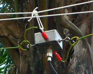
I'm experimenting with antennas again and wanted a way to string up a dipole so that I could easily pull it down and make adjustments.

My best antenna is a dipole tuned for PSK31 on 14.070Mhz that is over the roof of the house but while playing with a simple wire dipole between some trees next to the house I noticed it it appeared to pick up less electrical hash and it got me wondering if I should try suspending the dipole out beside the house where I currently have an end fed long wire (that picks up tons of noise).

This is a very simple idea, I'm positive others have used it too. I bought 30m of 3mm venetian blind cord and two little pulleys. (I already have a pulley up a tree from previous squid pole activities that was used to hold up the far end).

antenna hoist diagram.jpg
It's too early to tell if having the dipole away from the house is better than having it up higher but over the house but it's great to be able to drag it out and back in again for tuning. (I've got this dipole perfectly tuned on my second clipping).

Yes, I will need some weather proofing before leaving the balun out too long.

Sunday, April 13, 2008

Built an over-boxed QRP Power Meter

QRP Power Meter.jpg
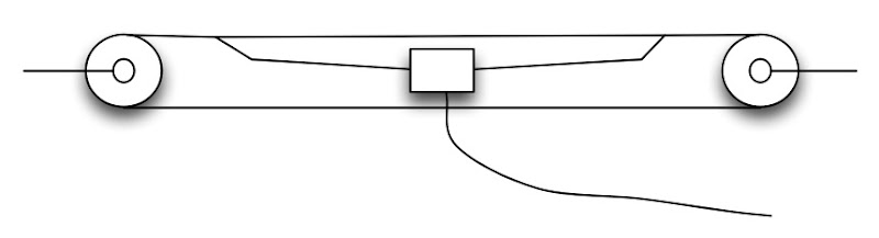
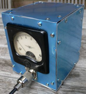
In preparation for the next NSW Home Brew group meeting at Dural where we will be having a power meter calibrate-athon, I've built a crazy box for my simple QRP power meter. Haven't tried to calibrate it but the output of a Pixie 2 (at 200-300mW) bashes the needle full over.

The box was constructed with 12mm angle aluminium at the edges and 0.5mm aluminium plate. That aluminium plate is probably a bit too thin but it's very easy to work with using simple tin snips. I was even able to cut the round hole for the meter with the snips.

All boxed up, it feels pretty sturdy and looks rather steam-punk.

The blue is a plastic protective layer that came on the sheet metal from Bunnings, I'll peel it off when it gets a bit scruffy.

I look forward to calibrating it in a few weeks.

Friday, March 28, 2008

80m Transceiver in an Altoids tin: Pixie 2

pixie2.jpg
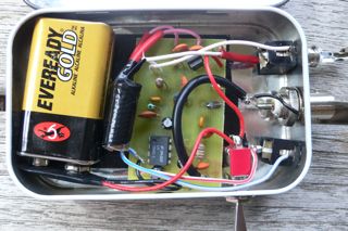
Just built a nifty little kit, the Pixie 2 from KennComm, a company that sells some very interesting bits and pieces..

A nice little kit, ideal for a beginner like me who keeps trying to learn Morse code (which of course is required to actually use this thing. I have it on 80m (3.58Mhz) but it can operate on any band up to 10m with some minor part substitutions.

US$29.95 plus some shipping if you are outside the US.

A nice little project for a cold afternoon. I do love these little things that people build into Altoids tins. Such a great form factor and so well shielded.

Wednesday, March 26, 2008

Harvesting parts from an inkjet printer

external.jpg
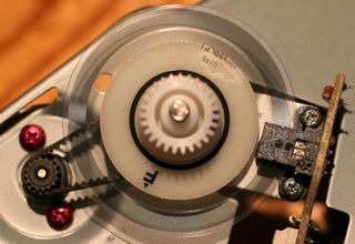
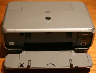
Ever since I attended a workshop on stepper motors at Dural conducted by Peter VK2EMU I've been watching for the site of an inkjet printer by the side of the road and this morning there was a rather wet Canon calling me...

After about half an hour of messing about the device was a wreck but these printers sure are a treasure trove of useful parts for the home robot maker: cogs, rollers, pulleys, switches, sensors and motors. Regrettably, this model doesn't use stepper motors but rather they seem to be DC motors with a rotary encoder linked to each one.wreck.jpg

The encoder disk is amazingly fine and it passes through an optical reader which I guess is rather like the encoder in a mouse. The markings are 7120 G516 but so far I haven't found a data sheet for them. The board has 4 wires coming from it so there's not too many options.encoder.jpg

Anyhow, despite my disappointment about the lack of steppers, I did score four very nice DC motors that seem to run well on about 3 volts and will be suitable for computer control or making little robots like this.parts.jpg

It's truly amazing the amount of perfectly good electronics that are available for free at council junk collection times.

Thursday, March 20, 2008

Got AD9851 Direct Digital Synthesiser working.

There's a lot of interest in ham radio circles around the new DDS chips which can act as a high stability VFO over a wide range with very fine control.

DDS CRO.jpg
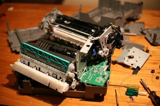
After hearing about them at a NSW Home Brew meeting, I purchased an AD9851 on eBay and have had about a week of frustration trying to program the thing. You need to send them a clocked 40 bit sequence to set the frequency.

I have been playing with a variety of Atmel AVR processors on various boards and in the end I found some wonderful software for the AVR Butterfly board by Stephen Weber, KD1JV, which has several versions including one for a transceiver and another for a straight VFO. (I'm using the VFO version). Programming was via an AVR ISP MkII rather than the serial protocol, I'm sure either would be fine.

The AVR Butterfly board includes a display and a 4 way rocker switch (plus push) that is used to control the frequency.

DDS Display.jpgNext steps are to put this in a nice box with more robust buttons, output filtering and amplifier. In summary, this gives the builder a very flexible oscillator for not many dollars. It's certain to become a core part of many future radios coming out of the Marxy lab in the future.

So, thanks so much to KD1JV for his excellent software, supplied with source, that has got me started and thanks to members of the NSW Home Brew group including John VK2ASU for his encouragement and offer of a chip in case I'd "smoked" mine.

An AVR Butterfly is about US$20 (a bargain) and I paid AU$50 for the AD9851 plus 30Mhz oscillator and a carrier board, which I consider pretty good all up.

DDS in box.jpg
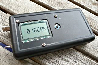
I've put this prototype in a little box to serve as a portable digital signal generator. Tried to run it off two AA batteries but the voltage was a little low for the 30Mhz oscillator to work reliably. (The AVR Butterfly is perfectly happy at low voltage though).

Tuesday, February 26, 2008

A great low power FM transmitter

FMTransmitter.jpgSaw this little FM transmitter for the broadcast band on the Make Blog.

I often want to listen to the Sunday ham radio broadcast but it would be great to not have to sit by the rig for the whole duration so I've used an iPod FM transmitter to relay the audio but they have very short range, even with an antenna added.

Turned out I had all the required components in my junk box. Built the oscillator first and it just worked right off, then built the buffer stage.

This circuit has an RF buffer stage so touching the antenna won't pull it off frequency. Running on a 9V battery it puts out enough power to cover the house. It's getting hard to find a spare frequency but I put it down near 88Mhz and it works very nicely.

I really love the aesthetic of "ugly" construction and it's so quick to throw together these little projects. I did release the smoke on the buffer transistor by accidentally using a 1K bias resistor in place of the 100K but after a small explosion that was fixed.

This design is to be recommended, it worked without any problems (except those of my own making) for me other than a bit of stretching of the oscillator coil to get it on band and it seems exceptionally stable given the construction.

If you tap the board it transmits a lovely metallic "clang" sound from the coil but that's to be expected.

I remember many years ago building JostyKit transmitters which had the coil etched onto the circuit board.

Saturday, February 16, 2008

Built a PVC pipe laptop stand

LaptopStand.jpg
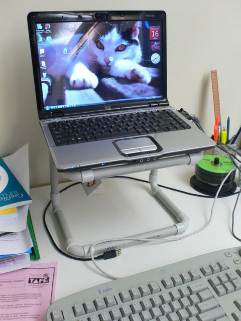
I'm using a laptop at work and have been searching the shops for some contraption to lift the laptop up so the screen is at eye height (I'm using an external keyboard and mouse).

Couldn't find anything I liked but searching on the net turned up a simple design for a stand constructed of PVC pipe. Marvellous stuff! Easy to cut, easy to join. I'm not using glue or anything, just friction will hold it together enough and still leave it with the ability to be pulled apart for carrying in my bag.

It droops forward a little (in the configuration shown here) which is fine. The laptop feels pretty secure on there but I am considering wrapping some rubber bands around the corners to give a little extra grip.

This little project went so well, I decided to make one for my wife as well (ideal romantic gift for Valentine's day I thought).

Monday, January 21, 2008

Coffs Harbout Radio Expo

Attended the Coffs Harbour radio expo on Sunday.

While a lot smaller than the Wyong field day I'm looking forward to in a few weeks, it was a fine event with lots to look at including some excellent home brew electronics and a diverse trash and treasure sale.

I've been looking for an RF signal generator and was very pleased to pick up a nicely built Electronics Australia design which includes a frequency counter for $25.

There were lots of books on sale and I purchased a slightly damaged copy of the RSGB Radio Communications Handbook at a good price. A great read.

The home brew display, which regrettably didn't have anyone with it to talk to when I was there, had a fascinating 80m double side band transceiver and a little portable whip with antenna tuner built in - rather like those suspicious "miricle antennas" you see advertised.

Lee Andrews was there selling rigs and seemed to be having a good time, it's a pity he doesn't get to Dural from time to time if only to keep his mood positive.

A great day, I'll be back next year with any luck. Photos.

Wednesday, December 26, 2007

Variable DC regulator V1

I'm getting really sick of those little "wall wart" power bricks for everything. My collection is getting silly, particularly as the multi-voltage ones seem to never quite have all the voltages I want.

My recent purchase of an Asus EEE PC is a good case in point, I imported it from Hong Kong so it has a power brick with a dodgy mains adapter plug on the back of it. This device needs 9.5V DC to charge - none of my existing adapters will provide this - hence this week's mini project.

It's a classic LM317 variable DC regulator in a box with a knob. The circuit is straight from the data sheet here. In my version I have 100R for r1 and the potentiometer is 1K. On the input I have a bridge rectifier so I can plug either polarity in to it without fear. Construction is on a tag board, probably a heatsink and some ventilation holes will be needed but the LM317 is well protected against over temperature and current problems.

I'm calling this project version 1 as it turns out it can't supply the 2.3A needed to charge the EEE PC, still useful for other things, but a version 2 is going to be needed for my original objective. Looks like I need an LM150 or LM138 for that.

Saturday, December 15, 2007

80m loop antenna experiment failure

Just a brief post about some experimentation that has failed.

I've been trying to build a loop antenna for 80m (3.5Mhz) to reduce local electrical noise.

The idea was a 2m diameter square loop built from 1m lengths of electrical conduit. First I built with 1 turn and a 300pF polyvaricon capacitor and it resonated nicely at about 20Mhz. Next went to 3 turns and it seemed to resonate around 9Mhz, then 4 turns and I can't get this thing to resonate at all.

No idea what I'm doing wrong or why this won't work. The family is a little bemused about the structure in the back yard - I tried to pass it off as my version of a Xmas decoration.

I did learn a bit about conduit - there are two main kinds around, electrical and water. Water pipe is designed to carry water under mains pressure so it's much stronger.

Update: Check out Alan's excellent response. I will get back to this project soon.

Sunday, October 07, 2007

Getting started with PSK-31 on Mac

PSK-31 is a recent digital mode that is very efficient in terms of bandwidth use and is excellent for keyboard to keyboard chatting on noisy HF.

I've been listening around for the distinctive warble sound on 80m and 40m for some time and hadn't found anything I could decode, then I read about 14.070Mhz (20m) and that seems to be where the action is. Several strong stations were heard without trouble.

A simple wire dipole for 20m was constructed and strung between two trees. I have a Yaesu FT-817 portable rig which has a mini-din 6 data jack on the back so an interface box (pictured above) was constructed. As I run a Mac the excellent cocoaModem software is in use. To key the transmitter, (as the FT-817 doesn't support VOX on the data port - a great pity) I first tried making a simple vox circuit but in the end used cocoaPTT which toggles the RTS line on a USB serial cable. One diode was used to save the radio from the +ve swing, so it just pulls PTT low to transmit, otherwise no electronics, just soldering, seems to work fine.

I called CQ, running just 5W into a very flaky antenna and was immediately called back by JA2LCN in Ogaki City, (this person seems very active).

If you run Windows there is lots of software about for PSK31, there's also some Linux software with a reasonable GUI.

In use, you leave the radio tuned to 14.070Mhz and watch the waterfall display. When you see a signal you click between the lines and start reading. It seems like a very nice way to chat, particularly if you can touch type. (A lot of receive errors I noticed now seem to be bad typing in retrospect).

I note there's some interesting kits around for minimal, low power transceivers designed for PSK31 use specifically. It's interesting to consider that a little board like this, a roll of wire, antenna tuner and a laptop and you can chat half way around the world pretty easily.

Saturday, September 01, 2007

Ultra high quality headphone amplifier

I read Alastair's post about high quality headphones with great interest. 

After finding the excellent Headwize site, I rushed down to Jaycar this morning for bits, and built the cmoy headphone amplifier (in an Altoids tin, with space to spare, as shown above right).

What really got me was the data sheet for the OPA2134 operational amplifier from Burr-Brown which says, in part, "The distortion produced by OPA134 series op amps is below the measurement limit of all known commercially available equipment."

Further: "THD+Noise is below 0.0004% throughout the audio frequency range, 20Hz to 20kHhz".

My experience.. 
  • This is easy to build. I did a hack job, as you can see above, and it worked perfectly first time.
  • I'm driving Sennheiser HD 212Pros.
  • Ripped some CDs at AAC 256kbps as sample content.
  • iPod shuffle has noticeable hiss
  • iPod 30Gb has less noise
  • Switching the headphones between the iPod direct and via the amplifier makes the iPod sound relatively dull.
It's hard to explain, but this little amplifier gives a real sparkle to the sound. It's not artificial or boosted in any way, but things like cymbals sound quite different - better. Sometimes there is too much bass for my liking.

Other notes:
  • Jaycar don't advertise the OPA2134, I went to buy the NE5534AN which is in their catalog and they gave me what I really wanted as a substitute - excellent! (AU$3.95)
  • This chip is broadband, when I touch the input it picks up all sorts of hum, I expect that it will be susceptible to RF from things like mobile phones and will need to be in a well shielded box (Altoids tin for example) with filtering to avoid picking up hash.
  • I used "ugly construction" which works well for RF projects so it's probably pretty stable as it's all ground plane.
  • Didn't bother with gain control as I figure whatever is driving it has it's own volume control. Mine has a bit too much gain for my listening levels.
So, one more thing to carry on the train.. thanks Alastair.

Update

I've spent a very entertaining evening re-importing some of my old favourite CDs at 256Kbs/AAC and of course listening to tracks in different headphones. There is a story around about how your brain works harder listening to music which has been compressed for space (no, not level - that's another topic). Basically masked parts of the audio are removed to reduce the data rate, but in fact you miss those parts of the signal and have to imagine them yourself.

In my youth I was very interested in "hi fi" and well remember the arms race that would follow the upgrade of one component in the system: a new moving coil cartridge would show up the noisy amplifier, upgrading that would show up the speakers, and so on.

Recent years have seen my music move totally on to computers and mostly in to headphones. Loud speakers are always a compromise existing as they do in a room that resonates to some extent. Little computer speakers have advanced tremendously in recent years and work damn well at low level. Headphones can reveal detail and texture in an audio track that will be missed on even the most high end speaker system.

With the falling cost of storage it's now time to re-import my CD collection at a higher bit rate - or perhaps I should just bite the bullet and go loss-less at last.

Update 2

Hmm, not sure if the higher bit rate AAC is worth it for me. I created this test which chops back and forth between 128Kbps and 256Kbps every ten seconds and I can't tell the difference. Of course I'm getting old and probably not listening in the best equipment.

Monday, July 30, 2007

Free stepper motors

Another entertaining meeting of the Amateur Radio New South Wales Homebrew Group on Sunday at Dural. Peter O'Connell VK2EMU presented an introduction to the use of stepper motors.

He explained how they work, (by stepping normally 200 little steps per revolution), how they are wired (4 wire, 5 wire, 6 wire arrangements), and how to drive them with a few darlington transistors and a PC parallel port.

It will be a great loss when no computers are available with parallel ports any more but I guess the wide availability of USB chipsets will help here.

A few interesting projects were discussed such as a plotter that can directly cut the copper on a circuit board to make printed circuit boards without etching, and home built milling machines for manufacturing.

The great thing about stepper motors is that they are one piece of precision equipment that can be obtained free. All of those ink jet and laser printers that get left out on the curb during council junk collections contain one.

Show and Tell was great too, Graham VK2GRA showed how he was using electric fence insulators for dipole construction, Stephen showed off his excellent 80m AM challenge transmitter, and Alan VK2ZAY had built a 2M AM transceiver in an Altoids tin plus a fantastic tiny short wave receiver.