Wednesday, May 28, 2008

Finally robotic beings rule the world

robotSafety.jpgTook some time out today to visit National Manufacturing Week here in Sydney at Darling Harbour.

What a fantastic show!

The best bits for me were the surface mount assembly machines, the printed circuit fabricator that uses a flat drill bit and stepper motors (for under $10k take home), and of course the robots.

There were huge metal benders, cutters - both laser and plasma, lathes and even some fine industrial footware.


Here's one of the robots in action, I like the warning label that is shown above.

I've put a gallery here.

Thursday, May 22, 2008

Social networking and the future of customer care

Had a chat on ABC Radio National with the very hip Steve Cannane this morning about how social networking is starting to be used for pro-active customer care. Check it out here.

iPhone in Australia with dual sims?

My Vodafone contract has expired and naturally I'm waiting for the iPhone to come to Australia before signing up again.

Just had a call from Vodafone asking me to start a new contract. Told the guy I was waiting for the iPhone and he said he was too.

He said a few other interesting things, all just from this outbound sales rep..

  • Vodafone will have about one month of exclusivity in Australia
  • New iPhones will have slots for dual sims, one for data and the other for calls
  • Launch in Australia is mid June


As I said, just claims by an outbound sales rep.

Friday, May 16, 2008

Web controlled Icom radio using python cgi

Modern radios have serial remote control interfaces but they're a little difficult to use. There is a wonderful library called hamlib but for some reason I can't get it to build at the moment on my Mac.

A remote control radio is a wonderful thing, I wish there were more around. You can listen to your own signal from far away to see how it really sounds and if the remote receiver is in a quiet location with a decent antenna it might be much better than listening from your home QTH.

Picture 3.pngI've set up a simple web page controlled remote receiver. The audio is streamed using Nicecast which is a great implementation of a streaming mp3 server that can be received using lots of different software on all platforms. One neat feature is that it automatically configures the port forward on my router.

Initially I used an external USB audio input device but after about 18 hours the sound deteriorated. I think there's a bug in the Mac's USB audio chain somewhere.

For the web interface I chose a very simple cgi using python.

Unfortunately I can't really offer this up to the world as I pay for upload on my internet connection and I'm already on target to run out this month.

I hope others can build on this and set up some more remote receivers around the place.

Here's the little python cgi:


#!/usr/bin/env python
# By VK2TPM Peter Marks http://marxy.org
# You are free to use this for any purpose.
#
# Thanks to df4or.de for notes on CI-V here:
# http://www.plicht.de/ekki/civ/civ-p31.html
#
# The BCD utilities come from
# Rigserve by Martin Ewing
# http://sourceforge.net/projects/rigserve
#


import serial
import time
import cgi
import sys
import time
import string
sys.stderr = sys.stdout

SERIAL_DEV = "/dev/cu.PL2303-000013FD"
SERIAL_BAUD = 4800
INTRO = "\xfe"
TO_ADDR = "\x70"
FROM_ADDR = "\xe0"
SET_OPERATING_FREQ = "\00"
SET_OPERATING_MODE = "\x06"
READ_OPERATING_FREQ = "\x03"
READ_OPERATING_MODE = "\x04"
EOM = "\xfd"

STREAM_URL = "http://XXXXXXXXXXXXX/listen.m3u"
SCRIPT = "/cgi-bin/radio.py"

def main():
log = open("log.txt", "w")
log.write("started %s\n" % time.ctime())
ser = serial.Serial(SERIAL_DEV, SERIAL_BAUD, timeout=1)
form = cgi.FieldStorage()
if form.has_key('frequency'):
freq = form.getvalue("frequency")
log.write("freq = %s\n" % freq)

setFrequency(ser, float(freq) * 1000)
if form.has_key('mode'):
mode = form.getvalue("mode")
log.write("mode = %s\n" % mode)
setMode(ser, mode)
else:
log.write("no form submit\n")
freq = getFrequency(ser)
mode = getMode(ser)
if mode == "LSB":
mode1 = "SELECTED"
mode2 = ""
mode3 = ""
elif mode == "USB":
mode1 = ""
mode2 = "SELECTED"
mode3 = ""
elif mode == "AM":
mode1 = ""
mode2 = ""
mode3 = "SELECTED"

htmlTemplate = """<html><head>
<title>VK2TPM</title>
<style>body,td,a,p{font-family:arial,sans-serif}</style>
</head><body>
<h1>VK2TPM Web controlled radio</h1>
<form action="$script">
<table>
<tr><td>Frequency:</td><td><input name="frequency" value="$freq">Hz
<a href="$script?frequency=$freqDown&Submit=Submit">-5</a>
<a href="$script?frequency=$freqUp&Submit=Submit">+5</a> </td></tr>
<tr><td>Mode:</td><td><SELECT NAME="mode">
<OPTION VALUE="LSB" $lsbSelected>LSB
<OPTION VALUE="USB" $usbSelected>USB
<OPTION VALUE="AM" $amSelected>AM
</SELECT></td></tr>
</table>
<input name="Submit" type=submit value="Submit"> <a href="$script">Refresh</a>
</form>
<a href="$script?frequency=3700&mode=LSB">3700 LSB</a> |
<a href="$script?frequency=3670&mode=AM">3670 AM</a> |
<a href="$script?frequency=3600&mode=LSB">3600 SSB</a> |
<a href="$script?frequency=576&mode=AM">576 AM</a> |
<a href="$script?frequency=11750&mode=AM">11750 AM</a> | <br />
<a href="$script?frequency=5643&mode=AM">5643 AM</a> |
<a href="$script?frequency=8867&mode=AM">8867 AM</a> |
<a href="$script?frequency=4426&mode=USB">4426 USB</a> |
<a href="$script?frequency=8176&mode=USB">8176 USB</a> | <br />
<p>Click to listen to the stream <a href="$streamUrl">here</a>.</p>
This receiver is connected to a 40/80m trap dipole so is best around 3500 and 7000.<br />
The stream is buffered by a few seconds so don't panic after you change something.<br />
After some tidying up, I'll publish the source on the <a href="http://marxy.org">blog</a>
</body></html>
"""
template = string.Template(htmlTemplate)
html = template.substitute({ "freq": str(freq),
"freqDown": str(freq - 5),
"freqUp": str(freq + 5),
"script": SCRIPT,
"streamUrl": STREAM_URL,
"lsbSelected": mode1,
"usbSelected": mode2,
"amSelected": mode3})

print "Content-type: text/html\n\n"
print html
ser.close()
log.close()

def test():
print "started"
ser = serial.Serial(SERIAL_DEV, SERIAL_BAUD, timeout=1)
print getFrequency(ser)
print getMode(ser)
setFrequency(ser, 3670 * 1000) # Hz
ser.close()

def setFrequency(ser, freq):
fs = "%010d" % int(freq)
print fs

out = bcd4(int(fs[8]),int(fs[9]),int(fs[6]),int(fs[7]))
out += bcd4(int(fs[4]),int(fs[5]),int(fs[2]),int(fs[3]))
out += bcd2(int(fs[0]),int(fs[1]))
print out

sendStr = INTRO + TO_ADDR + FROM_ADDR + SET_OPERATING_FREQ
for byte in out:
sendStr += chr(byte)
sendStr += EOM
ser.write(sendStr)

echo = ser.read(len(sendStr))
print "got reply of %d chars" % len(echo)

def getFrequency(ser):
sendStr = INTRO + TO_ADDR + FROM_ADDR + READ_OPERATING_FREQ + EOM
ser.write(sendStr)

echo = ser.read(len(sendStr))
print "got reply of %d chars" % len(echo)

if not expectChar(ser.read(), INTRO): return
if not expectChar(ser.read(), FROM_ADDR): return
if not expectChar(ser.read(), TO_ADDR): return

byte = "0"
result = ""
while byte != EOM:
byte = ser.read()
print "%02x" % ord(byte),
result += byte

print "got EOM byte"
frequency = 0.0
if len(result) > 0:
f=0
for k in [10,11,8,9,6,7,4,5,2,3]:
f=10*f + nib(result,k)
frequency = (float(f) / 1000)
return frequency

def getMode(ser):
sendStr = INTRO + TO_ADDR + FROM_ADDR + READ_OPERATING_MODE + EOM
ser.write(sendStr)

echo = ser.read(len(sendStr))
print "got reply of %d chars" % len(echo)

if not expectChar(ser.read(), INTRO): return
if not expectChar(ser.read(), FROM_ADDR): return
if not expectChar(ser.read(), TO_ADDR): return

byte = "0"
result = ""
while byte != EOM:
byte = ser.read()
print "%02x" % ord(byte),
result += byte

print "got EOM byte"
mode = "XXX"
if result[1] == "\x00":
mode = "LSB"
elif result[1] == "\x01":
mode = "USB"
elif result[1] == "\x02":
mode = "AM"
elif result[1] == "\x03":
mode = "CW"
elif result[1] == "\x04":
mode = "RTTY"
elif result[1] == "\x05":
mode = "FM"
elif result[1] == "\x06":
mode = "Wide FM"
elif result[1] == "\x07":
mode = "CW-R"
elif result[1] == "\x08":
mode = "RTTY-R"
elif result[1] == "\x11":
mode = "S-AM"
return mode

def setMode(ser, mode):

sendStr = INTRO + TO_ADDR + FROM_ADDR + SET_OPERATING_MODE
if mode == "LSB":
sendStr += "\x00"
elif mode == "USB":
sendStr += "\x01"
elif mode == "AM":
sendStr += "\x02"
sendStr += EOM
ser.write(sendStr)

echo = ser.read(len(sendStr))
print "got reply of %d chars" % len(echo)

# non-reversed
def bcd4(d1,d2,d3,d4): return (16*d1+d2, 16*d3+d4)
# pack 2 BCD digits
def bcd2(d1,d2): return ( (16*d1+d2), )

# get a 4-bit nibble (digit) from a nibble string
def nib(s,i):
k = ord(s[i/2])
if i%2 == 0: k = k >> 4
return k & 0xf

def expectChar(byte, expected):
"""Return true if we got what we expected"""
if byte == expected:
print "good %02x" % (ord(expected)),
return True
else:
print "wanted %02x unexpected %02x" % (ord(expected), ord(byte)),
return False

main()

Measuring small inductors with a bridge

meter2.jpgYou might gather from this blog that I'm most comfortable with digital things - computers, software and even embedded microcontrollers seem very predictable to me. However, I'm very interested in learning the dark arts of radio frequency construction.

There's a long term project on the bench here, a double sideband transmitter for 14Mhz. Everything was going quite well until I got to building a tuned circuit. Of all the components, small inductors are the most mysterious to me.

I mentioned my frustration to John Ha1e, VK2ASU, at a recent meeting of the NSW home brew group and he kindly offered to help me out.

John showed me how he measured small inductors, such as ones wound on drinking straws, using an inductance bridge. There are a number of circuits around the net, I built the excellent simple one by Drew Diamond, VK3XU from his first volume of "Radio projects for the amateur". A design based on his circuit is published here I just discovered.

Yes, it really dips on small inductors like the one shown above. In this picture it's not showing the dip as it would be boring to show a meter on zero! I have yet to calibrate this instrument but I think it can measure from about 1uH up.

meter1.jpg


As with all of my home brew, they look pretty messy when you open the case - but that's where the beauty is for me.

It's amazing how valuable it is to actually watch someone winding and measuring small tuned circuits, but after watching John at work I gained the confidence that these things do actually follow the laws of physics and now feel I'm on my way again.

Thankyou VK2ASU and VK3XU.

Update: It looks like I can measure from about 1uH to 10uH on this device. I went out this morning and purchased a collection of 10% inductors. There's something funny about the colour codes on inductors, the colour seems rather different to those on resistors for some reason.

Monday, May 12, 2008

A Chat podcast 23

Get the podcast in iTunes, or here.

  • Neil Young and the Java?

  • Alternative firmware for Canon point and shoot cameras

  • OLPC in Australia

  • Home broadband upgrade


Thanks Ben for production. Sorry my earlier quick show notes post looked bad.

Sunday, May 11, 2008

Controlling an AD9851 with an Atmel AtTiny85 (or other)

avrdds.jpg
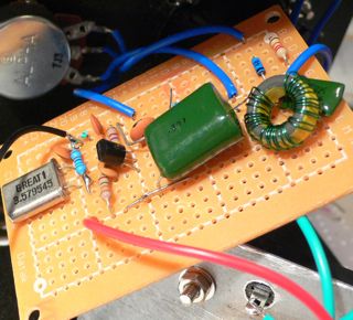
Following on from my last post, I got something similar working with an ATTiny85. This sample code does a slow sweep from 10Mhz up a bit. It's just a demo, the bit I've been looking for myself and couldn't find was how to just say sendFrequency().

I have lots of ideas for applications of these things, including:


  • General purpose VFO with keypad and knob

  • Sweep test generator, paired with a digital rf signal measurer for computer plotting filters etc

  • Automated antenna analyser with a digital SWR measuring thingy


This code is written in C and uses avrlibc. I'm working on a Mac but it will work the same on Linux or that other OS that was quite popular.


/*
Control an AD9851 DDS with an ATMega85
*/

#include <avr/io.h>
// Sets up the default speed for delay.h
#define F_CPU 800000UL
#include <util/delay.h>
#include <math.h> // for pow()

// Pins used to talk to the DDS chip
#define LOAD 4
#define CLOCK 3
#define DATA 0
#define LED 1

#define DDS_CLOCK 180000000UL

#define OUTPORT PORTB
#define OUTPORTDIRECTION DDRB

void sendFrequency(unsigned long frequency);
void byte_out(unsigned char byte);
void outOne();
void outZero();
void bitSetHi(volatile uint8_t *port, int bit);
void bitSetLo(volatile uint8_t *port, int bit);

int main (void)
{
OUTPORTDIRECTION = _BV(LOAD) | _BV(CLOCK) | _BV(DATA) | _BV(LED);
unsigned long freq;

// flash an led to show we're alive
int i;
for(i = 0; i < 10; i++)
{
bitSetHi(&OUTPORT, LED);
_delay_ms(100);
bitSetLo(&OUTPORT, LED);
_delay_ms(100);
}
while (1)
{
// Do a frequency sweep in Hz
for(freq = 10000000; freq < 10001000; freq++)
{
sendFrequency(freq);
_delay_ms(1);
}
}
return 0;
}

void bitSetHi(volatile uint8_t *port, int bit)
{
*port |= ( 1<<bit );
}

void bitSetLo(volatile uint8_t *port, int bit)
{
*port &= ~( 1<<bit );
}

void sendFrequency(unsigned long frequency)
{
unsigned long tuning_word = (frequency * pow(2, 32)) / DDS_CLOCK;
bitSetLo(&OUTPORT, LOAD); // take load pin low
int i;

for(i = 0; i < 32; i++)
{
if ((tuning_word & 1) == 1)
outOne();
else
outZero();
tuning_word = tuning_word >> 1;
}
byte_out(0x09);

bitSetHi(&OUTPORT, LOAD); // Take load pin high again
}

void byte_out(unsigned char byte)
{
int i;

for (i = 0; i < 8; i++)
{
if ((byte & 1) == 1)
outOne();
else
outZero();
byte = byte >> 1;
}
}

void outOne()
{
bitSetLo(&OUTPORT, CLOCK);
_delay_ms(1);
bitSetHi(&OUTPORT, DATA);
_delay_ms(1);
bitSetHi(&OUTPORT, CLOCK);
_delay_ms(1);
bitSetLo(&OUTPORT, DATA);
_delay_ms(1);
}

void outZero()
{
bitSetLo(&OUTPORT, CLOCK);
_delay_ms(1);
bitSetLo(&OUTPORT, DATA);
_delay_ms(1);
bitSetHi(&OUTPORT, CLOCK);
_delay_ms(1);
}


The AMQRP board has it's own regulator and has a 5V output so I'm powering the ATTiny85 from that power rather than a separate input. Here's a nifty spot reference. Simple enough even for me to build.

spotGen.jpg

Saturday, May 10, 2008

Controlling an AD9851 DDS with an Arduino

ad9851.jpgBeen playing with the AD9851 DDS for a while now using other people's software mostly written in assembly language that I find rather hard to get my head around. Finally tonight, with the help of several others who have published their work on the internet I have got some simple code to drive this chip the way I want.

This can tell it the frequency the generate in Hz and it just works.

This minimal example does a small sweep from 10Mhz so it's easy to listen to on a radio.

While I prefer to use the atmel chips "naked" I do find the Arduino board a very convenient way to muck around and get things going in an interactive environment. This code doesn't rely on any magic Arduino libraries so it should be easy to port, I'll post a straight ATMEGA version soon.

The code presented here shows some things I've struggled to figure out: how to calculate the tuning word from the frequency and how to send the serial commands to the chip. I hope this helps someone else.


// Control a AD9851 DDS based on the good work of others including:
// Mike Bowthorpe, http://www.ladyada.net/rant/2007/02/cotw-ltc6903/ and
// http://www.geocities.com/leon_heller/dds.html
// This code by Peter Marks http://marxy.org

#define DDS_CLOCK 180000000

byte LOAD = 8;
byte CLOCK = 9;
byte DATA = 10;
byte LED = 13;

void setup()
{
pinMode (DATA, OUTPUT); // sets pin 10 as OUPUT
pinMode (CLOCK, OUTPUT); // sets pin 9 as OUTPUT
pinMode (LOAD, OUTPUT); // sets pin 8 as OUTPUT
pinMode (LED, OUTPUT);
}

void loop()
{
// Do a frequency sweep in Hz
for(unsigned long freq = 10000000; freq < 10001000; freq++)
{
sendFrequency(freq);
delay(2);
}
}

void sendFrequency(unsigned long frequency)
{
unsigned long tuning_word = (frequency * pow(2, 32)) / DDS_CLOCK;
digitalWrite (LOAD, LOW); // take load pin low

for(int i = 0; i < 32; i++)
{
if ((tuning_word & 1) == 1)
outOne();
else
outZero();
tuning_word = tuning_word >> 1;
}
byte_out(0x09);

digitalWrite (LOAD, HIGH); // Take load pin high again
}

void byte_out(unsigned char byte)
{
int i;

for (i = 0; i < 8; i++)
{
if ((byte & 1) == 1)
outOne();
else
outZero();
byte = byte >> 1;
}
}

void outOne()
{
digitalWrite(CLOCK, LOW);
digitalWrite(DATA, HIGH);
digitalWrite(CLOCK, HIGH);
digitalWrite(DATA, LOW);
}

void outZero()
{
digitalWrite(CLOCK, LOW);
digitalWrite(DATA, LOW);
digitalWrite(CLOCK, HIGH);
}


The board I'm using is the excellent carrier from AmQRP.

Friday, May 09, 2008

Switched home broadband to Telstra

cableGuy.jpg
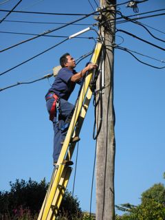
We've had Optus cable internet here at the house for many years. It's been a reliable service but over time annoyances build up in a relationship like this so I decided to upgrade and switch to Telstra Bigpond on a service they claim can deliver up to 30Mbps down and 1Mbps up.

Optus gave me 8Mbps down and 256kbps up. The slow upload did cause me some grief sending mail and uploading.

These days Telstra sends out contractors to do any "hard" work and in this case it was Silcar Communications. The guys did a great job and didn't mind me taking a few pictures as the job progressed.

They had to run another cable from the pole as I refused to let them cut over the Optus cable.

I'm pretty happy with the performance so far, of course it will be interested to see how it degrades in busy times. Here's my test results from ozspeedtest.

Broadband Speed Test Results

Test run on 09/05/2008 @ 02:38 PM

Mirror: Telstra Bigpond
Data: 9 MB
Test Time: 3.28 secs

Your line speed is 23.02 Mbps (23024 kbps).
Your download speed is 2.81 MB/s (2878 KB/s).

I'm seeing some pings under 10ms to Australian sites and I really do get 1Mbps upload which is great.

I refused the netgear wireless router they offered and just took a motorola cable modem and I chose to use my Airport Extreme which seems to be working nicely.

It's always amusing to see how these folks respond to a house without windows. They are drilled in the art of telling windows users to reboot to make things work. I said, this is a Mac, you don't need to reboot.

So, why did I switch from Optus:


  • They decided to charge me $2 per month because I wouldn't agree to direct debit. I always pay promptly by bpay and I'd be happy to have electronic invoicing, but no dice.

  • A sales person came to the door trying to sell me a worse deal than I was currently on, much less data, a little more speed and more money.

  • When my modem died in a storm, I purchased a replacement on ebay (from another optus customer), despite this they insisted on sending out a tech to read them the Mac address - something I can certainly do, and charged me the same amount as a replacement modem.


Oh and don't try writing to them about anything, when I did I just got back a form letter FAQ. I don't think they even read letters from customers. Oh well, bye bye Optus. Let me know when you're rolling out fiber.

Update: Cancelling Optus was a good experience. When you ring to cancel you get the 'A' team, the retention people. He said, "you should have rung us first, we could have given you $30 a month for 6 months". I explained that I had rung, and written, and had not been satisfied.

Anyhow he was able to cancel me right away and refund my latest payment. "Speed isn't everything" he said. You're right there, I thought...

Update 2: We are now without a home phone. The plan was also to churn our home phone over to Telstra today as well. The tech was due to come in "the morning", at 2pm they rang to say that they couldn't come and needed to re-shedule. I suggested next week.

Our home phone has been disconnected by Optus, not sure if it's related to the internet switch-over or the churn of the line to Telstra. Very annoying. Currently talking to Optus via Skype.

Ok, Optus has turned it back on. Strange that a churning phone can be disconnected before being connected to the new carrier. I guess I'm being punished for being pesky.

Sunday, May 04, 2008

Rough guide to surface mount soldering

smd.jpgI share an interest in good quality headphone audio with many including Alastair who purchased the board and parts for the Alien DAC. Not being too confident with the soldering iron he made a deal, he bought two sets, one for him and one for me, if I'd help him construct his one.

Surface mount components are either tiny themselves, like the resistors and capacitors, or if large, they have pins that are very close together and hard to avoid having the solder bridge between them. The move to computer manufacturing with surface mount components is unfortunate for us home constructors. Some parts are only available in surface mount packaging and I fear for the future of this fine past time.

I got both boards going and thought I'd share my tips on construction, which you can see from the image are not too good, but serviceable.

For the chips with many pins, hold down the chip with the point of angle ended needle nosed pliers (the weight of the tool will hold it in place - hands shake too much), tack solder one corner pin and one on the opposite corner, then remove the pliers. Just flow solder across all the pins on each side, then go back with fine solder wick and suck back all the excess solder.

For resistors and capacitors again use the point of angle ended needle nosed pliers to hold them in place while soldering one end.

I think I'll put my new audio output device in a nice box along side a powered amplifier as covered in the past. Thanks Alastiar for the bag of bits!