Wishing to free myself from using crystals in
small transmitters, the
DDS-60 board (with a AD9851 chip) seemed like the way to go, but how to do the frequency entry?
I've played with the excellent
AVR Butterfly DDS controller, but it's a little fiddly for regular use.
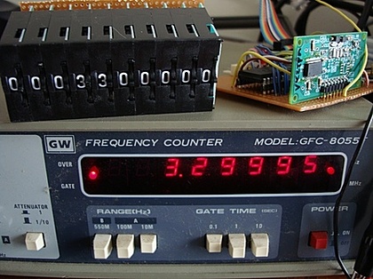
BCD thumb switches seem like a nice approach as they remove the need for a display. Here's how it looks:
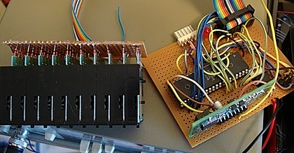
And here's my rather messy prototype board with the BCD switch wiring.
I wanted lots of I/O pins for scanning the BCD switch array (12 wires) and talking to the AD9851 DDS chip (3 wires) so I chose an Atmel
ATmega32.
As frequency in the CPU isn't important, my design just uses the internal 8Mhz oscillator.
The code is written with avr-gcc, uses
avr-libc and burnt with
avrdude, all on a Mac. (Installed with Darwin ports).
I scan the BCD switches and if the value has changed I write to the DDS. There's a single LED that I flash when I write. (It's fun debugging code when you only have a single LED to let you know what's going on).
Note that there is a bug in MacPorts which won't build avr-libc. The tip about how to get past this is
here.
The hard bit is driving the DDS chip and that code is
here.
UpdateFigured out a problem that might bite others, I was trying to use port c pins which were set for JTAG mode in the CPU fuse bytes, thanks to
AVRFuse this was easily fixed.
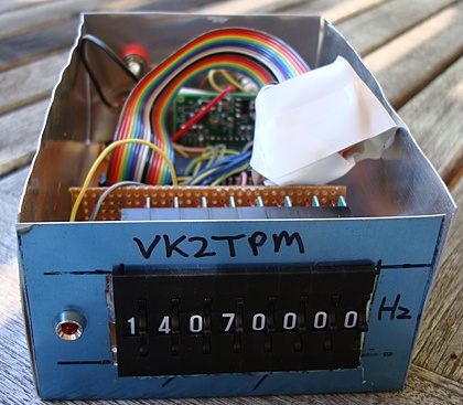
I also realised that I have too many digits, so next step is to remove excess and put all this in a box. Done:
Here's the code:
/* Scan 8 BCD switches and set a DDS to the frequency
   Peter Marks VK2TPM
   http://marxy.org
*/

#include <avr/interrupt.h>
#define F_CPU 800000UL
#include <util/delay.h>
#include <math.h>   // for pow()

#define LED_BLINK_MS 500
#define SCAN_DELAY_MS 20

#define SCAN_LOW_PORT	PORTA	// low 8 digits scan output
#define	READ_BCD_PORT	PORTC	// read BCD bits 0-3

#define LEDOFF          PORTB &= ~(1<<2)
#define LEDON           PORTB |= (1<<2)

// Pins used to talk to the DDS chip
#define DDS_LOAD 6
#define DDS_CLOCK 5
#define DDS_DATA 4

#define DDS_CLOCK_HZ 180000000UL

#define DDS_OUTPORT PORTD
#define DDS_OUTPORTDIRECTION DDRD

void ioInit();
unsigned long scanFrequency();
void blinkLed();
unsigned long tenPower(int decimal);
void sendFrequency(unsigned long frequency);
void byte_out(unsigned char byte);
void outOne();
void outZero();
void bitSetHi(volatile uint8_t *port, int bit);
void bitSetLo(volatile uint8_t *port, int bit);

int main()
{
	ioInit();
	blinkLed();

	unsigned long lastFrequency = 0;
	unsigned long newFrequency = 0;

	while(1)
	{
		newFrequency = scanFrequency();
		if(newFrequency != lastFrequency)
		{
			sendFrequency(newFrequency);
			blinkLed();
			lastFrequency = newFrequency;
		}
	}

	return(0);
}

// Scan the BCD thumbwheels and return the frequency
unsigned long scanFrequency()
{
	int i;
	unsigned int readBcd = 0;
	unsigned long frequency = 0;

	for(i = 0; i < 8; i++)
	{
		SCAN_LOW_PORT = (1 << i);
		_delay_ms(SCAN_DELAY_MS);
		readBcd = PINC & 0x0f;
		_delay_ms(SCAN_DELAY_MS);

		if(i == 0)
			frequency = readBcd;
		else
			frequency += (readBcd * tenPower(i));
	}
	SCAN_LOW_PORT = 0;
	return frequency;
}

unsigned long tenPower(int decimal)
{
	unsigned long result = 10;
	int i;
	if(decimal == 0)
		return 1;
	for(i = 0; i < decimal - 1; i++)
	{
		result *= 10;
	}
	return result;
}

void blinkLed()
{
	LEDON;
	_delay_ms(LED_BLINK_MS);
	LEDOFF;
	_delay_ms(LED_BLINK_MS);
}

void ioInit()
{
	DDRA = 0xff;	// enable output
	DDRB = 0xff;	// enable output
    DDRC = 0xf0;	// C is input on lower 4 bits
	DDRD = 0xff;	// D is for DDS control
}

// DDS control code
void bitSetHi(volatile uint8_t *port, int bit)
{
    *port |= ( 1<<bit );
}

void bitSetLo(volatile uint8_t *port, int bit)
{
    *port &= ~( 1<<bit );
}

void sendFrequency(unsigned long frequency)
{
  unsigned long tuning_word = (frequency * pow(2, 32)) / DDS_CLOCK_HZ;
  bitSetLo(&DDS_OUTPORT, DDS_LOAD); // take load pin low
  int i;

  for(i = 0; i < 32; i++)
  {
    if ((tuning_word & 1) == 1)
      outOne();
    else
      outZero();
    tuning_word = tuning_word >> 1;
  }
  byte_out(0x09);

  bitSetHi(&DDS_OUTPORT, DDS_LOAD); // Take load pin high again
}

void byte_out(unsigned char byte)
{
  int i;

  for (i = 0; i < 8; i++)
  {
    if ((byte & 1) == 1)
      outOne();
    else
      outZero();
    byte = byte >> 1;
  }
}

void outOne()
{
    bitSetLo(&DDS_OUTPORT, DDS_CLOCK);
    _delay_ms(1);
    bitSetHi(&DDS_OUTPORT, DDS_DATA);
    _delay_ms(1);
    bitSetHi(&DDS_OUTPORT, DDS_CLOCK);
    _delay_ms(1);
    bitSetLo(&DDS_OUTPORT, DDS_DATA);
    _delay_ms(1);
}

void outZero()
{
  bitSetLo(&DDS_OUTPORT, DDS_CLOCK);
  _delay_ms(1);
  bitSetLo(&DDS_OUTPORT, DDS_DATA);
  _delay_ms(1);
  bitSetHi(&DDS_OUTPORT, DDS_CLOCK);
  _delay_ms(1);
}
The circuitThe BCD switches have small diodes from each of the outputs 1,2,4,8 to a common bus which goes to a 4k7 pull down resistor and to input pins. (If I built this again, I'd reverse the diodes and use the CPU's internal pull-up resistors to save some wiring).
Output pins directly drive the common on each BCD swich to scan them with a brief +5V.
There's a 7805 3 terminal regulator to regulate 12V down to 5V for the CPU, the 12V line goes direct to the DDS-60. The input has a forward diode to protect against reverse polarity. One pin has an LED with a 1k resistor that flashes on power up and on each frequency change.
I brought out the programming pins on a little header. Also I had a go at a serial interface but haven't got it working yet.
UpdateHey, cheers to
NT7S blog and thanks for the encouragement!
 Stand by for a report of this all crashing down on the roof, but for now at least, I've managed to raise the centre of my 40/80m dipole another metre up over the roof of the (2 story) house.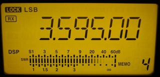




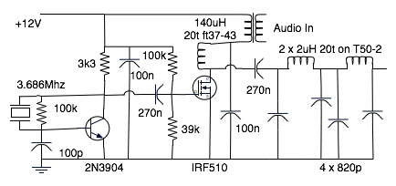
 This feeds into some sort of beacon transmitter. Anyhow, the whole setup works rather well and I know the audio sounds fantastic on air.
 Anyhow, we had a nice breakfast, a friendly chat and I learned a bit about WSPR and WSJT.
 I've just spent three and a bit days helping my step-mother to get on to email for the first time in her life.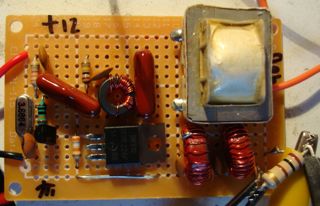



 The
The  Stephen talked about where to pick up common valves even today and showed some of his past projects which are beautifully constructed.


 Last night we were fortunate to have a wonderful experience - we sat in on a bit of a rehearsal of the
 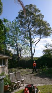 Today is tree lopping day. We're getting rid of a pesky liquid amber and a pine tree. Both of these shade the garden.
 I'm pleased to report that I've built a real application in Django on Google App Engine.

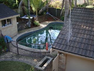
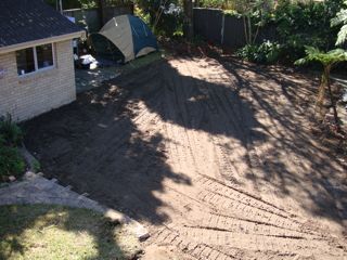
 Last week's demolition of the back yard went so smoothly (if a little behind schedule) that I was starting to think that I had the knack of dealing with trades people.
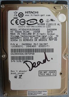 We seem to lose a laptop hard drive about every twelve months and yesterday my daughter lost the drive in her MacBook.
 I remember being really scared by the Daleks as a young child, and I've always had a soft spot for

 I've been pretty active on 14MHz again lately, mostly PSK31 where I chat with VK2ATC, VK2VFV, VK2PN, and if he gets back on, VK2ZAY. It's an amazing mode where, this morning I chatted with UA0QGG in Russia on just 5W.