
Wednesday, October 23, 2024
Tech news spot on ABC Radio
Sunday, October 20, 2024
3LO turns 100

I've heard that everyone who was asked to perform was more than keen to be there. Aside from amazing musicians there were many notable celebrities in the crowd.
The first guest was no less than the Prime Minister, Anthony Albanese, who was wearing ABC Sox.
Some names that stood out for me included: Brian Nankervis, Colin Denovan, David Anderson, Deborah Cheetham Fraillon, Jacinta Allan, Jacinta Parsons, John Pesutto, Jon Faine, Mark Seymore - (hunters & collectors), Paul Higgins, Pete Smith, Peter Couchman, Raf Epstein, Red Symonds , Sarah Blasco, The Teskey Brothers, Tina Arena, TISM, Vicka & Linda Bull, and Virginia Trioli.
Danny Tran was there doing interviews for a TV news spot. Daniel Ziffer was sitting behind me. (I wanted to tell him how much I enjoyed his coverage of Sam Bankman-Fried's hair).
The show opened with the ABC news with the theme played live. Here are a few clips:
The Athenaeum Theatre was a wonderful venue for all this.

WIA historian Peter Wolfenden, VK3RV, kindly sent me this list of the first stations:

Warm thanks and congratulations to the team that put all this together. A memorable event.
As well as those of us who've worked at 3LO in the past, the current staff gathered for a photo:

John Amies wants to know why Peter Evans wasn't there.
Wednesday, October 16, 2024
Comms Connect Show in Melbourne
Today I joined some other amateur radio operators at the Comms Connect trade show at the Melbourne Exhibition Centre. Check in was efficient. Ralph VK3ZZC, Peter VK3YPG and Nigel VK3DZ were there too.

It was mostly pretty dry commercial stuff but Icom was there and even had some amateur equipment on display. Knowledgeable Craig Norris was there with all the Icom news.

Kenwood had a stand but there was no amateur gear, mostly DMR commercial stuff.

Telstra had some sort of life-saving drone idea but "it's going to have to be at least three times bigger than this" to be useful.

After the show we went for a very nice Yum Cha and then headed for one of Nigel's family bars "The Sherlock Holmes Inn".

Very nice. My thanks to Ralph for the bag of semi-conductors and happily I had a bag of NE602s for him.
On the train home I ran in to Ray VK3ACR, the world if full of Amateur Radio operators if you pay attention.
Monday, October 14, 2024
QRP Kits Easy Receiver
As a refreshment after all my recent home brew activity I built a nice little direct conversion receiver kit from QRP Kits aka "Pacific Antenna".

It's a classic NE602 + LM386 direct conversion receiver as described in Experimental Methods for RF Design. I've built these before. This version ads an RF bandpass filter to the front end and has an unbalanced audio chain to the LM386. It drives headphones just fine but is a little soft into my bench receiver.
Even though it only covers a small portion of the band - you move that portion with the trimmer capacitor - tuning is very sensitive and they do suggest that a multi-turn pot would be a good idea. I find it drifts a bit. Some of the supplied capacitors had very tiny and indistinct markings but the kit went together well and it worked on first power up.
Here it is receiving a parks operator:
The documentation is good and available on the web page. My kit arrived here in Melbourne, Australia, three weeks after ordering. Pretty good.
With a bit of board trimming I was able to fit the receiver into a low cost compact case.


"Socketry" this is called.
It seems more stable now that it's boxed up securely.
Wednesday, October 09, 2024
Tech news spot on ABC Radio.

Also Pig butchering scams are targeting Australians and are social media platforms really biased against conservative users?
Listen here:
https://www.abc.net.au/listen/programs/nightlife/nightlife-tech-talk-with-peter-marks/104446916
Sunday, October 06, 2024
Dremel cut PCB construction
Prototyping small circuits where it's not worth designing and etching a board can be done in many ways. I've used "ugly" (which I think is rather beautiful) where components float above the copper ground plane; MePads where small copper pads are superglued to the base plane; or strip board with track cuts.
Recently I've converged on a system that's working quite well for me.
The circuit is drawn out in pencil and the outline of the PCB rectangle is traced.
Working through what should not be connected to what, I draw the cut lines under a spaced out version of the circuit. Here's my drawing and below the final working board.

I mark up the board with the planned cuts.

To make the cuts in the copper, I lay the Dremel with a cutting wheel on the bench and lean it so that it just cuts the copper. I draw the board along the wheel, leaving the Dremel stationary. I can get pleasingly straight cuts this way. It is worth checking for non-conduction between areas with a multi-meter as sometimes a strand of copper can be left at a corner.

To hold components against the board for soldering you need some sort of "helping hands" but the one I learned about from an Adam Savage video is called Omnifixo. They are not cheap but are well worth it for all the cleverness.

For years I've been using a little, rather low power, bench soldering iron but I find that quite a lot of power is needed when soldering to large copper areas. I have switched to a 70W iron and it is a revelation.
Naturally, I first had the transistor in the wrong way around, but after that was fixed. The joy of oscillation was experienced.

I'm sure this is not news to any readers but I thought it worth documenting for some who might be getting started with home construction. It's not as compact as other techniques but lends itself to making changes.
One other thing I do these days is add an LED (and resistor) to the power line. It looks nice and I can't tell you how much time I've wasted wondering why an un-powered circuit doesn't work!
Friday, October 04, 2024
Experimenting with an SSM2167 compressor limiter board
The home brew AM transmitter on the bench at the moment has thrown up the issue of either low or over modulation from my mic audio. Some time ago, I purchased a couple of interesting boards described as "SSM2167 Preamp Compressor Limiter Noise Gate Dynamics Processing Module DC 3V-5V Microphone Preamplifier". They are under AU$5 from AliExpress and really tiny.

To aid with experimentation, I've mounted mine on a carrier board.

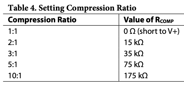
R1 on the board controls the noise gate, which I'm not too interested in. R2 controls compression and came with a 1k resistor in place. The data sheet has this table:

With the un-modified board I fed a 1kHz tone in and get peak to peak voltages:
50mV -> 440mV
100mV -> 880mV
200mV -> 1.43V
Higher inputs do not give higher output. The output waveform looks pretty good, so not clipping. Gain is rather low for my dynamic mic however.
I replaced R2 with a 100k resistor and it has much more gain.
5mV -> 880mV
10mV -> 960mV
20mV -> 1.06V
Output level stops there and again gain is being reduced.
Stephen, VK2BLQ, brought this idea to my attention as it has been discussed as helping the uBitx radios.
Wednesday, October 02, 2024
First contact with home brew AM transmitter on 7.125
For too many weeks I've been tinkering with a small transmitter for the active AM frequency of 7.125Mhz and just now I called CQ and was kindly answered by Ross, VK3ARW. He reported good signal strength both where he is (west of Bendigo) and on the Ironstone ridge SDR in South Australia. The transmitter is home brew (although I used a Jaycar mic preamp kit).
I've been testing by listening to myself on the PKLoops SDR.

The transmitter uses an Arduino Nano that simply boots up and tells an Si5351 to put out 7.125MHz. There's an RF buffer using a 2N2222. The magic happens, the generation of AM, using a simple diode ring mixer that is set to be off balance. Mic audio, from the preamp, is fed in and out comes AM. (This technique was mentioned by Dave, VK3ASE, who also uses it). There's another 2N2222 gain stage then a low pass filter. Next I have the three stage RF power amp from Drew Diamond's 80m transmitter. Finally another low pass filter for 40m.
To answer Ross's question.. out of all this I get about 1.5W so, for the sake of getting some contacts I've fed this in to a little RF amp that gives about 25W peak.
I must say I'm astonished that I didn't get RF feedback or other instability given the construction. Despite Ross's kind words on the audio I can see that a peak limiter is needed to keep modulation up without over-modulating.
Subscribe to:
Posts (Atom)