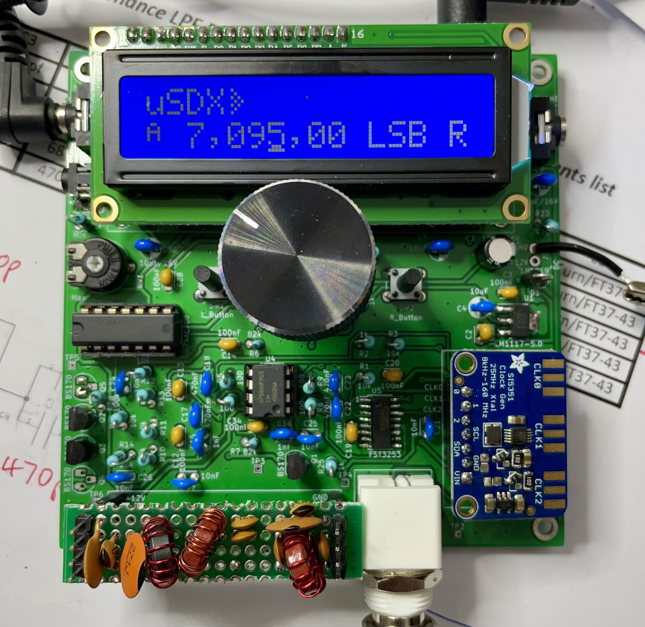
The transmitter is a very efficient class E design and PWM modulation combined with amplitude modulation gives a passable single sideband signal. The circuit can cover many HF bands and there's a place to plug the appropriate low pass filter. (In the photo above I'm just receiving and have simply jumped the LPF).
While you can purchase a QCX and modify that, I've purchased a specially designed board.
There is a Wiki site about the project here. There is an active discussion group about the project on groups.io here. Within the files area is a downloadable Bill Of Materials (BOM) with the parts to build it. I was able to upload that CSV file to DigiKey and very quickly all the parts turned up. The only extra part needed was an Si5351 carrier board which I already had in the junk box.
I ordered the WB2CBA designed PCB from "too_brute" in the Netherlands via Ebay but it took ages to make it to Australia so you might check the discussion group for a source closer to your location. My board is the V1.02 revision.
Construction is fairly straightforward although you need to read about the earlier revisions of the board. There is one surface mount chip to solder to the main board. The most challenging part for me was the reworking of the Si5351 board. You have to remove some surface mount components and then add back two resisters and two zero ohm resistors as links. I used a hot air gun and needle nosed pliers to remove the components.
The software is here and can be built with the Arduino IDE.
Initially, I took the easy way out and programmed the CPU by writing the hex file to the chip which was plugged in to an Arduino UNO. I used a USBASP and the avrdude command line tool on macOS.

avrdude -c usbasp -p m328p -u -U R1.02j.hex
As you can see I've used R1.02j. One minor note is that my tuning knob goes backwards so I see there is a small change that can be made in the software to reverse it.
Now, building from the Arduino source, I commented out the QCX define and have reversed the ROT pins to read:
#define ROT_A 7 //PD6 (pin 12)
#define ROT_B 6 //PD7 (pin 13)
My uSDX didn't work on first power up... I had the power protection diode in backwards. Easy to diagnose and fix. Note that you need to adjust the display contrast otherwise you'll see nothing.
What an amazing age we live in. Guido has achieved amazing functionality in a low power CPU (slightly overclocked to 20MHz). Here's his block diagram of the hardware, and most of all, software taken from here.

(Click diagram to enlarge by the way).
Changes needed to make it work
My uSDX was working but turned out not to be on the right frequency. I'm using the Adafruit Si5351 board which is said to have a 25Mhz crystal on it, rather than the 27MHz one in the source code. Changing #define F_XTAL 25004000 still had me quite a lot lower than expected.
I measured the frequency on clock 0 of the Si5351 and instead of 7.xMHz it was 6.58Mhz.
I've now set F_XTAL to 24000000 and my frequency is close to correct. Here it is receiving a station on 40m with my terrible interference in the background.
Now I've added a rather rough low pass filter for 40m.

Transmit works but sounds terrible:
Looking around YouTube I found another user's off air recording. It's better than mine but still not great.
Update: Later software, where is "m"?
I noticed that people were talking about defines like SWAP_ROTARY that I don't see in the latest release software. The trick is to switch to the "feature-rx-improved" branch.
Update: Reset settings after changing defines in code
If all else fails, read the documentation. Even though I was changing the F_XTAL define in the source code it wasn't taking effect as I expected. It turns out that the Si5351 crystal frequency is stored in flash memory and can be displayed and adjusted in menu 8.1 where it's called "Ref freq".
At some point I had inadvertently set the frequency to 24Mhz and that value had been saved in non-volatile memory. The trick to reset stored settings is to push the rotary encoder in while powering on. The display tells you it is resetting all settings.
Update: Incorrect low pass filter!
I was probing around on the transmit side, where I get almost no power out, and have now realised that I've put the wrong sort of low pass filter on the little plug board. What is needed is a "serial resonance low pass filter". Here's a copy from that site:

Update: Decent power out now
After all the above, I was still only getting a few mW of power out. I removed a few of the BS170 FETs used in the class E output, thinking that I might have destroyed them, but they tested OK. I did break the leads on one of the FETs though.
I found this thread on the group about modifications to the WB2CBA V1.02 circuit to make it work with software revision m. Essentially:
- Remove Q5 and short pins with solder blob.
- Remove R28
- Set menu item 8.2 to 20 and 8.3 to 205
This done and CW at the antenna looks like this with 2 FETS rather than 3:

34V peak to peak into 50 ohms, about 3W. Here's how me saying hello in sideband looks:

Here's how the audio is sounding:
Next step, as pointed out by John, VK2ASU, is to have a contact. I've been calling CQ a bit and can see and hear myself on a nearby SDR station. My signal is the one on 7.10. It looks a little wide but the suppression of the other sideband looks good.

Update: A contact on the Kandos net
The audio in this clip was recorded on the VK3KHZ OpenWebRX located at Croydon, Victoria about 30km away.
I came up on the tail end of the popular Kandos net on 40m and as you'll hear had a good contact with Brenton, VK3CM who gave a very generous report for my 3W into an end fed antenna here. Brenton looks to be about 300km from me so I'm very happy with that.
Here's the uSDX's built-in morse decoder working rather nicely:
Here's a bit more sideband reception on 40m:
8 comments:
Hi Peter,
Congratulations on the detailed description. I like it when my own experiences are described on the website. I wish you a successful use.
73, Gyula HA3HZ
What happened displays showed
Resetting
Excellent , congratulations
Great to see your build, my pcbs have just arrived. Note that the processor is not being overclocked as the ATMEGA 328 is speced to run at 20MHz, as are most of the ATMEGA range. Just thought it worth mentioning. I have overclocked them in the past above this but its makes a bit of a job refactoring all the timing registers and baud rates etc. It works OK to around 24MHz.
Are there through hole components under the Si5351 board?
Really good job, thanks!
In my case, a chinese uSDX transceiver, the tuning knob is also reversed. Is it easy to fix it (not great ability in soldering/desoldering)?
Or should I deal with the issue?
Thanks again!
Hi,
I've just built the very same uSDR. What is the most up-to-date software for it?
Paul
Post a Comment