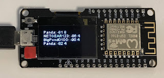
The library you need to drive it is here.
The trick is to download that Git repo as a Zip and then in the Arduino software install the library from local Zip.
The documentation for the display driver is there on GitHub if you scroll down.
There are methods for pixel drawing, text drawing, even some high level routines for building a user interface.
Of course, if you haven't already, you'll need the esp8266 board files by following the instructions here. Choose generic esp8266 and on macOS the serial port was SLAB_USBtoUART.
Out of the box the board was programmed with the simple example from that site, which is a pretty impressive display of text in various fonts and graphics. When I tried the example I got nothing.
After some hair pulling and gnashing of teeth, I figured out that SDA and SCL are reversed for this board compared to the examples on GitHub.
This works: SSD1306Wire display(0x3c, SCL, SDA); // reversed!
Having Wifi and a display suggested a simple Wifi network display project. The esp8266 wifi library is documented here.
Another thing to watch for is that the display is really a pixel graphics display so the x,y locations for text must account for the line height of the text.
#include "SSD1306Wire.h"
#include "ESP8266WiFi.h"
// Initialize the OLED display using Arduino Wire:
SSD1306Wire display(0x3c, SCL, SDA); // reversed!

void setup() {
  WiFi.mode(WIFI_STA);
  WiFi.disconnect();
  delay(100);

  // Initialising the UI will init the display too.
  display.init();

  //display.flipScreenVertically();
  display.setFont(ArialMT_Plain_10);
  display.setTextAlignment(TEXT_ALIGN_LEFT);
  display.drawString(0, 0, "Starting.." );
  display.display();
}


void loop() {
  // clear the display
  display.clear();
  int height = 10;
  // WiFi.scanNetworks will return the number of networks found
  int n = WiFi.scanNetworks();
  if (n == 0) {
    display.drawString(0, 0, "no networks found");
  } else {
    for (int i = 0; i < n; ++i) {
      int y = i * height;
      String ssid = WiFi.SSID(i);
      String rssi = String(WiFi.RSSI(i));
      String encryption = "Unknown";
      switch(WiFi.encryptionType(i)) {
        case ENC_TYPE_WEP:
          encryption = "WEP";
          break;
        case ENC_TYPE_TKIP:
          encryption = "WPA";
          break;
        case ENC_TYPE_CCMP:
          encryption = "WPA2";
          break;
        case ENC_TYPE_NONE:
          encryption = "Open";
          break;
        case ENC_TYPE_AUTO:
          encryption = "Auto";
          break;
        default:
          encryption = "Unknown";
          break;
      }
      String line = ssid + ": " + rssi + " " + encryption;
      display.drawString(0, y, line);
      display.display();
      delay(10);
    }
  }

  // Wait a bit before scanning again
  delay(5000);
}
Update
John, VK2ASU, points out that there is a similar board for the ESP32 for even less money here. The ESP32 is the successor to the ESP8266 and offers a faster and dual core CPU along with Bluetooth, Hall effect sensor and temperature sensor.


5 comments:
I've been trying to get my OLED to work for an entire day already, I'm not even going to ask how you figured out that SDA and SCL are swapped :D
Thank you very much for your detailed post!
I modified line and it worked hard -> SSD1306Wire display(0x3c, D6, D5); // reversed!
Thanks for your Post, It is excelente.
Carlos Bruni Brazil Bahia Salvador
Thank you thank you.
Pulling my hair out trying to get this board going...
Thank you; thanks a lot. My few remaining strands were spared.
Has anyone managed to use this with the display and an SPI connection? As far as I can see, their choice of I2C pins sits in the middle of the only usable SPI interface. The second SPI interface on the chip does not seem to be accessible for user peripherals
Post a Comment