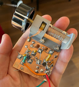
I built a DC receiver using the PTO VFO based on the "High School" receiver described by Bill, N2CQR, recently. It's a beautiful thing to behold but for various reasons (no NPO caps for one thing) my build drifts like mad. It would make a fine Theremin.
I mentioned this to Paul, VK3HN, and he commented that analog VFOs do drift. He had kindly sent me a sample VFO / Controller board he's been developing for his amazing home brew "Summit Prowler" rigs.
It's a nicely conceived board with an Atmel chip that can be programmed as an Arduino Nano, Si5351 clock generator - with output buffers, connections for a parallel LCD but also I2C, connections for a rotary encoder and spares for various buttons. I had promised to give him feedback on it many months ago.
Here's VK3HN's blog post about it. Here's the circuit. Here's his firmware.
Paul's code has all sorts of specialisation for his various rigs but my needs are much simpler so I've created a stripped back version that is just a VFO. Here's my code. I'm using a 128x32 OLED display instead of the LCD and have swapped in a different rotary encoder library.
The rotary encoder tunes and pushing the button changes the tuning step.
Feeding a TUF-1 mixer and then to a few transistor stages and an LM386 module it does actually receive although I have hum which is not uncommon with DC receivers. My "bench spread" construction doesn't help of course.
Arduino boards.txt
Thanks to Paul, VK3HN, for sharing his code and design.


Thanks for including the links Peter. This board was factory fabricated and populated at JLCPCB. Unfortunately they soldered in ATMega328 instead of 328P hence the need to set up a different board profile. When I do a Rev 2.0 I'll use a socket to avoid this problem and I have a bag on 328Ps anyway. Please note that there are various minor bugs on the board which I ironed out manually on the 5 PCBs I had made.
ReplyDeleteIf you try running your DC Rx from a battery it might help with the hum.
If you used a JMS-1 or SBL1 DBM in the mixer and as the si5351 goes all the way to 160MHz you can run your little DC Rx all the way up to 2m. You probably don't need a bandpass filter for the higher HF and VHF bands, could be worth trying.
Paul VK3HN.
Peter, Paul: Step back from your soldering irons. Stop with the negative vibes. Don't give in to the siren calls of the Si5351. It is possible to make that BEAUTIFUL analog discrete PTO that Peter built stable. Even down under! See: https://soldersmoke.blogspot.com/2023/02/vk2blq-builds-high-school-direct.html
ReplyDeleteSure, it will behave like a Theremin if you wave your hand near the coil. JUST DON'T DO THAT! And you might need a few NP0 or silver mica caps -- we can get those for you. But one of the main objectives of the project was to have a DC RX in which the builders could understand the workings of each component. You can't do that with an Arduino and an SI5351.
Peter's build is beautiful. Stick with it! Make it stable. I was listening to an Australian station with mine just the other day. THE RADIO GODS HAVE SPOKEN! TRGHS! 73 Bill N2CQR
Dear Bill,
ReplyDeleteI didn't mean any negativity! This is all great fun and lots to learn.
Thank you for your inspiration and encouragement. I shall order some NP0 capacitors.
Best 73s.
Just kidding Peter! All in good fun. I really like the looks of your PTO.
ReplyDeleteJust today Dean KK4DAS and I worked with the high school kids and managed to get EIGHT of these things oscillating. The students are off to a good start and will soon have their receivers built.
73 and regards to Paul VK3HN. Bill N2CQR
Peter and Bill,
ReplyDeleteI think I have the solution. Peter should build *both* VFOs, a PTO and an si5351, and switch between them in his DC receiver. This will provide the ultimate choice -- between authenticity and soul, and clinical digital icy perfection. He can then choose one or the other, depending on his mood. Maybe the slow drift and analog fluidity of the PTO will get under his skin, and eventually move him to a new appreciation of all things analog.
Perhaps...
Paul VK3HN.
Perhaps with some fancy programming you could make a PTO simulator. Just dial up a pre-stored drift profile according to whatever takes your fancy at the time.
ReplyDeleteCheers,
Steve VK2AAV