 I'm very inexperienced at home building radio projects. Inductors, in particular, seem rather mysterious to me. Microprocessor projects seem much more predictable, signals are either on or off, but radio circuits may or may not be resonant, may or may not oscillate, and they certainly change whenever you try to measure anything.
The book "Experimental methods in RF Design" by Wes Hayward and others (aka EMRFD) it truly an inspiration and after reading it for months, and a few false starts, I've just completed the very first project in the book, a 40m (7MHz) direct conversion receiver with just two active components.
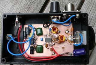
The design uses an NE612 oscillator/mixer to do most of the job and an LM386 as an audio amplifier suitable for driving headphones. NE612s don't have a lot of dynamic range so the only gain control is a pot at the antenna that serves as RF attenuator and overall "loudness" control. This works really nicely.
I can't reproduce the circuit here, but it's Figure 1.9 in EMRFD and uses only a handful of components. The design is very similar to this one.
My implementation is very ugly construction and I've mounted it in a rather over-engineered box with a transparent lid - I thought it might be a good bit of home brew art to show at the Wyong show.
Challenges
This project has taken some time to get started. First I soldered a trimmer and an off the shelf inductor the the board and attempted to confirm to myself that it was resonant at 7Mhz. I couldn't get a dip on my dip meter and couldn't see any sensible voltage peak when sweeping an RF oscillator. I was stumped for weeks.
(Thanks to VK2ZAY for his encouragement during this frustrating stage).
So I decided to follow the instructions...
I wound my own inductor using a toroid but still had trouble coupling to it. In the end a single loop of wire (soldered into a loop) running through the toroid and then around the coil on my dip meter worked and resonance was found. A few extra capacitors later and it was in the right place. This is a major breakthrough for me!
Next I built the circuit for the oscillator (active components inside the NE612). Holding a short wave radio near the circuit and sweeping the tuning cap quickly showed that it was indeed oscillating nicely.
Finally, an LM386 was ratted from another project and the audio stage built. It all worked on the bench, and would receive my GDO, so I installed it in a box and powered it from external batteries.
It stopped working.
Turns out the NE612 is a little voltage sensitive and my re-chargeable 4 AA battery pack had dropped in voltage. Fresh batteries and it now works.
The sound is very pleasant and there's no doubt that it's very satisfying to listen to a radio you've constructed yourself. Here's a recording of ZL2JR from New Zealand and some tuning around here.
Wow, that's great mate. I'm glad you got it all working. There is nothing quite like hearing the first signal on a receiver you built yourself.
ReplyDeleteWhile you tweak the circuit on the bench with a generator, and basically know it will work, hearing real signals is just different. Its as if the photons we test it with aren't quite as endowed with the "realness" of those produced some where else.
Its like First Light for a telescope. I never tire of building receivers - and I've built a lot.
Hi, congratulations, I tried to look for the schematics but couldn't find them.
ReplyDeleteCould you please mail them to me or put an image on your blog?
thanks in advance