Friday, May 03, 2024

Testing Unun losses

In his recent feedback, Richard, VK3TXD, suggested I measure the loss in the Unun built with Jaycar LO128 core by making a second one and wiring them back to back.


On the spectrum analyser, I set the range from 5Mhz to 30Mhz and the plot shows a very slow loss over the range. Note that the tracking generator is at -10dBm.


In the middle of the frequency range the loss, going through two transformers is 3.26dB. 1.63dB for one Unun. Richard commented that 2 turns of primary winding is not good so I added a turn. Here's the plot.


The loss in the middle of the range, going through two transformers is slightly less at 3.24dB. In my test, hardly measurable. Of course with an extra turn on the primary the impedance transformation is much less so more turns on secondary will be needed.

Perhaps I'm not measuring this correctly but I'm not seeing the dramatic problems that were predicted.

Thursday, May 02, 2024

Constructive feedback on my naive end fed half wave from Richard, VK3TXD

After posting the last story on my very simple end fed half wave antenna I received some suggestions for improvement from Richard, VK3TXD. In the past he has sent me some antennas and match boxes he has constructed. He was concerned that if he left this as a comment I might take it as heavy criticism, but no, I am very grateful for his suggestions.

Richard writes:

Some suggestions for you. In no particular order. Some terse notes. Do feel free to query, happy to discuss.

1. Check toroids before use. The Jaycar ones often have a sharp lip. Sand it off with emery type paper. Sharp lips are the enemy of enamel wire.

2. The cap. You mentioned HV. My experience with the altronics ones was poor. They were super lossy. I strongly suggest Silver mica. 500V is good for 100W and more. No need for higher.

    VNA measurement will show the difference easily.

    You used 150pf. That looks a little high.

3. I used 0.8mm diam enamel wire for 100W. I use 0.63 wire for 50W. Not sure what you used. Using 1mm or more is pointless. [I used 0.63mm]

4. The LO1238 is quite good. If anyone criticises you and says you should use a Fairrite core or similar, ask if they've done measurements. I have. The differences are within margins too close to error. Some people say you should use #52 or other material.  Same come back.

5. Spread out winding increases loss. It makes flux linkage between turns more difficult. Close wind. Shorter magnetic paths are better in all regards.

6. 2 turn primary tapping is not good. For 160m, 80m, 40m, the efficiency will be really poor. On 10m it starts to come good. Use a 3 turn primary. <<-- please test with VNA, the difference is quite surprising.

One thing. On 10m the 3 turn primary may be fractionally worse on 10m. On all other bands the loss will be substantially less.

    With 3 turn primaries, 160m and 80m are ok.

7. Teflon tape wrapping the toroid is pointless. Some people have a fetish for it. It will make the experimenter _feel_ good, but at 100W, it makes zero difference - I've not had flashover ever and never used tape. I think I've sold about 70 UnUns using the same toroid.

8. At 400W, yes, 400W, the 100pF 500v silver mica cap will fail. A user admitted that. I _really_ don't recommend it. I am not convinced the EFHW is a good solution to > 100W as the electric field will be very high, and the instantaneous voltage on the hot end of the UnUn will get disgusting-high.

9. Be prepared to need a 1:1 to tame the common mode current. The unit I sent you has an inbuilt 1:1. It is not perfect, the coax sits in the high intensity field, but no user has reported a problem.

Craig VK3NCR tried a 1st version without the 1:1 and on 10W from his IC705 it garbled voice peaks. His radio hated it. The 2nd version with 1:1 cured it.

   1:1 baluns and common mode current seems to be a dirty little secret few own up to.

10. On 13th May for a few days Stan VK3BOT is going mobile. He is using my UnUns. https://www.vk3frc.org.au/post/an-invitation   if you get a chance to have a QSO and mention me. VK3NCR and VK3BOT

11. There are some other good options for toroids......

Try stacking 2 LO1234's = super glue together. This has a shorter magnetic path and the efficiency is quite a bit better than the LO1238. How much better.....use the VNA <smile> This one is in fact my favourite,


Try stacking 3 of the LO1230 (smaller ones) and use 0.63mm wire. I put 50W into these. These are very efficient also. I did a mounting sled for use in a jiffy box. It is quite good.

12. Oh. On YouTube checkout "mm0opx" - he's done a lot of work. Also "evil lair electronics". And "Steve Ellingtn" has a nice video on the small compensation coil you can use to make the bands line up better.

13. I've not really mentioned my thoughts on efficiency and antenna mounting. Let me know if you are interested. The above data-dump is a bit intense for now.

14. My favourite so far. The 2 stack LO1234.

Tech notes. 

The smaller diameter has a shorter magnetic path which aids efficiency. Being taller helps increase the magnetizing impedance but not so much as to make 10m unusable.

Below is based on 2 stack LO1234 UnUn with 2 stack 1:1 as well. It goes into a rather nice and small box. Stan and Craig have them now. Drilling the ends is disgusting, it is super tight tolerance so I made drilling templates. I'm happy to send you files if you want - personal use etc. Oh. I've been using some stainless wing nuts and bolts recently. Some users want them.


My sincere thanks to Richard for his detailed feedback and suggestions. I will certainly try some of them.

I put up the antenna this afternoon and had a QRP contact on 20m with a station west of Sydney (about 800km away). I mentioned this to Richard who replied:

Having success with a home built antenna is THE BEST isn't it. I find it a pleasure. I bet you smiled! <I would have>

The resonance moving up the band to 100% normal and caused by capacitive coupling being frequency dependent (don't quote me on that)...as F goes up, more coupling to ground hence resonance goes up. Something like that.

That Steve Ellington Video I mentioned. Chase that down. Seriously. He explains it well and a small loading coil 2m from the UnUn will fix it <<<---worthwhile (and fun). I use some 19mm (?) placcy pipe and about 8 to 10 turns.

Why 2m along? Steve explains. It is all to do with the current profile moving by each band and hence the loading coil has a different effect by band. You can get it quite close to spot on.

One thing. The SWR being that low quite often means there is a fair amount of loss in both efficiency of the UnUn, but also in radiation. Unless noted, your coax will be on the ground and its outer sheath is acting as the radial and radiating into....the ground. Hence loss.

I've nec modelled the EFHW. Very naive models tho. A good thing about it is that on 40m, wth 20m of wire, the point of highest current is 1/2 way up the wire. If you are using a  9 or 10m squid pole and inverted L, it is nice and high in the air and the pattern is quite NVIS. On 20m, the high current point is lower and it looks more like a vertical with lower lobes, hence you get the best of both worlds - 40m NVIS and 20m DX. It all depends on mounting etc of course.

I like to have the 1:1 in the same box and use 2, yes 2, radials. I found the SWR was better. I mount in inverted-L with a 1 to 1.5m elevation of the unun. The radials radiate, so get them into the air.

That capacitor looks good actually! It may be a SM type. In truth...this only comes into play marginally on 20m rising to significantly on 10m.

The spec-an if it has a tracking generator can do a loss measurement. The nanovna can save the file tho. The spec-an may offer it - I don't know.

You can open a .s2p file with a text editor. It is just all the measurements that were used to plot the data. It is in complex (real imaginary - or real and phase angle) format. See Dan's post on the math.

On the NanoVNA. Download a PC program (or mac?) and use that connected to the nanovna. That will have a means to save the data to file. It is of type ".s2p" and from that I can plot swr and loss with the code I wrote with help from Dan as mentioned.

Use the 'logmag S21' test - and be sure to calibrate and use the same fly leds in the calibration. Accurate measurement is not a trivia exercise.

NOTE....the 50 ohm side pigtails can make a big difference to SWR. I've found keeping these short makes a big difference..

The ohm meter test is all very well, but the EFHW can have quite high voltages on the top end of the UnUn. The ohm meter is not great for this kind of test, you are not testing with what it will experience. That is why at 400W I would get nervous. At 100W the voltage should be less than 500V even under an adverse SWR.

Ta on the neatness. I have wound many. Using 0.8mm wire makes it a lot easier.

Efficiency....the worst balun you could possibly make will have loss up in the 3db region, so losing 50% of the power. This will be turned to heat in the ferrite core. You might juuuuust her that kind of loss.

Guess, but from experiments, on 40m a 2 turn primary may have round 40% loss worst case. The 3 turn primary halves that and slightly better. The  stack of LO1234s is a bit better again.

I tried stacking LO1238's. That helped on 160 and 80 and 40. On 20m it was worse than 1 core and on 10m it was terrible. Looks good tho!

The hard truth. You won't hear the difference unless it is a marginal signal on SSB. A more efficient UnUn will get less hot, so even on 10W it will run a little cooler. SSB is very lenient. All change if you use digital. It makes a huge difference there. Core heating under digital can be over 10 times, and maybe 20 times more than SSB because of higher average power.

Feel free to publish. A very small mention would be fine. I'm sure you will write it better than me. You can make a few posts out of it exploring that compensation coil, and trialling the smaller 2 stack, and loss testing etc. I've spent a lot lot lot of time playing with all this.

Gotta go. I'm cooking dinner!

Cheers - Richard

Wednesday, May 01, 2024

Simple End Fed Half Wave antenna for 40, 20, 10m using Jaycar toroid

Just for fun, using parts already in hand, I've built a portable half wave end fed antenna that is resonant within each of the 40, 20 and 10m bands. It's built on a mains extension cord holder purchased a while back from Bunnings for not much money. The matching electronics is built in to the holder.


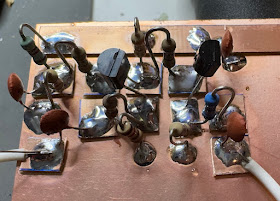
The Unun (or autotransformer) is 2 turns on the transmitter side and 13 turns in total. I don't know why many builders use the funky swap over half way through the winding - perhaps it's to keep the output away from the input? I used a simple approach.


The toroid core was purchased from Jaycar catalog number LO1238, branded "Duratech". There is a 150pF high voltage capacitor across the antenna connector.


It makes quite a convenient way to carry the antenna wire. The long wire was cut to 20m but needed to be shortened a few times to get it to resonate in the 40m band. About 1m of counterpoise wire is dropped on the ground.


It's a bit low on 40m but I didn't want to shorten further so that the other resonant points would be in higher bands. Here's 20m:


10m looks OK too:

A small antenna tuner will be able to match this to a transmitter on each of these bands without too much trouble.


Above is the plot with ham bands shown in grey.

A simple project with easy to find parts. I haven't seen these cable holders recently but hopefully there are similar low cost options.

References

Richard, VK3TXD, has interesting designs at Oz-Tenna and a useful introduction document here.

VK6YSF tests an Unun with the LO1238 toroid.

Some discussion on the EEVBlog.

HFKits describes a similar end fed matcher.

Sunday, April 28, 2024

Wireless sound mixing

I don't go out to see bands very much but recently we attended a dinner and show by The Martini Set. It was an enjoyable evening but what caught my eye was the sound guy walked around the room adjusting the mix, equalisation, and reverb with an iPad tablet.


The brain box up on the stage creates a wifi network that the tablet joins. He said it was quite robust and if there was interference bad things didn't happen. There was a spare tablet ready to go in case the main one died for some reason. Perhaps this is common now but it was news to me.


Thursday, April 25, 2024

Trying a $15 70cm transceiver HK-188

Peter, VK3YE, recently posted a video of a pair of 2.4Ghz transceivers he bought at Aldi for $20. They worked OK but had a number of obvious annoying problems including a lack of a display. 

Browsing Amazon I noticed a pair of 446MHz transceivers for $30 and I wondered what you get for the extra $10.


As you'll see in the video, they work very well, and I'd have to say the extra $10 is well rewarded. (Of course you don't have to spend much more to get a Quansheng radio!)

The radios are on 446Mhz, which is in the Amateur 70cm band so Richard and I are licensed to use them but I'm not sure how legal they are for the general public.

The manual is on the FCC website here. The biggest chip on the board has no label and is presumably the CPU / SOC and drives the LCD display.


I can see some inductors in the output presumably for low pass or antenna matching - a good sign. Components I can read are:

  • WX050 D812 4 pins
  • 26.000MHz crystal
  • BEKEN BK4818 BS3432FB 32 pins 
  • 4VZU 5 pins
  • M4890S UDE399 8 pins
The BK4818 is a half-duplex TDD FM transceiver.

"The BK4818 is a half duplex TDD FM transceiver operating from 115 MHz to 537 MHz band for worldwide personal radio. Besides speech communication, the BK4815N on-chip FSK data modem supports F2D and F1W emission to be used in FRS band for text message and GPS information exchange.

The BK4818 is a complete, small form factor solution optimized for low-power, low-cost, and highly integrated mobile and portable consumer electronic devices, requiring only a few external decoupling capacitors and an external inductor for input matching.

- World wide band: 115 ~ 537 MHz
- 12.5/25 kHz channel spacing
- On chip 5 dBm RF PA
- 3.0 V to 3.6 V power supply
- CTCSS tone receiver with up to parallel eight frequency detector
- 23/24 bit programmable DCS code
- Standard DTMF and programmable in-band dual tone
- SELCALL and programmable in-band single tone
- 1.2/2.4 kbps FSK data modem with either F2D or F1W modulation type
- Frequency inversion scrambler
- Voice activated switch (VOX) and time-out timer
- RF Signal strength measurement and signal quality measurement
- TX Audio signal strength indication and RX audio signal strength indication
- 3-wires interface with MCU with maximum 8 Mbps clock rate
- QFN 4x4 32-Pin package"

Quite a capable device.

This seems like a more sophisticated device than the Aldi one that Peter, VK3YE, reviewed.


(Image taken from VK3YE's video). The HK-188 has an LCD display which would add some complexity but not as much as I see in there.

Monday, April 15, 2024

PSSST kit build - Pete's Super Simple Sideband Transceiver

I've been a fan of Pete, N6QW, since hearing him on the excellent Soldersmoke podcast and blog.  Pete has built many home brew transceivers over the years. He has written for many respected ham radio publications. (I'm a bit confused about the best web site to give for Pete, it could be this, or this, or this or even this).

Pete's original description of the radio is here.

When Todd of MostlyDIYRF announced that he was creating a modular kit version of Pete's design for a 20m transceiver I eagerly ordered.

The kit comprises a collection of well designed modules that can be used in other experimental transceivers. Each module typically has input and output pads, designed for edge soldered SMA sockets and 0.1 inch spaced pins on an edge for plugging in to a mainboard. Where required DC power is supplied via these pins. Here's the 4.915Mhz IF board:


The boards are very high quality and come with a set of components and a page with circuit and some tips on assembly and testing.

Being able to build and test each stage separately has been a great help.

Here's the motherboard populated with what's needed for receive:


The IF is at 4.915Mhz, so the VFO starts at 14Mhz - 4.915Mhz = 9.085Mhz. There is a BFO that should be just below the IF frequency to mix with IF out to produce audio from the upper sideband signal.

The VFO and BFO oscillators are provided by a board with an Si5351 clock generator being controlled by a PI2040 CPU programmed with the Arduino runtime. Todd has shared the source code here.

The kit is version 1 and Todd makes it clear that this is not a project for beginners. Making a kit as complex as this is a very difficult task and there are a few things that could be improved in the future. 

There is a discussion group for builders on groups.io here.

At the time of writing, I've got receive working pretty well. I took some notes of what I've experienced so far.

  • My kit was missing two of the 0.1” x 4 sockets and two of the 90 degree headers.
  • The I2C LCD connections are not in the same order as the supplied LCD - VCC and Ground are swapped - danger!.
  • Note the errata about 5V power being needed for the LCD - I plan to re-compile the software for another LCD (Waveshare) that I prefer to use and runs off 3.3V.
  • The Mixer and BFO mixer are two of the same board but I was a bit puzzled as they have different names.
  • Pin 1 on the ADE-1+ is the one with the white dot kind of near it - the text is upside down.
  • The modules have three pins for each input/output, although not mentioned these are great for attaching SMA sockets. I wish the coax connections on the motherboard also matched SMA sockets to jumpers could be used.
  • Steerable amp missing a 3k resistor 
  • Missing 4 more 90 degree headers
  • IF module missing 220pf cap
  • On the driver and final board the pins on the regulator U1 are very close together 
  • T1 on the driver and final board isn’t specified but on the discussion group Todd reveals that it should be 10 turns bifilliar 
  • I chose to fit SMA sockets to each module. In a few cases there isn’t quite enough space for the socket and plug for example between the IF model and Audio output board.
  • My Digital VFO board as it came outputs 21Mhz on CLK2 and something like 40Mhz on CLK0 - not correct.

I downloaded Todd's source code for the board and built and installed it but still the frequencies and even the waveform didn't look right. After having a look I first considered forking Todd's code but realised I wanted to do a major re-structure of the project and so, with his blessing, I started my own version which is here on GitHub.

My changes include:
  • Re-ordering the source code to make it easier for me to follow
  • Replacing "magic" numbers in the code with const definitions
  • Improving the detection of no stored values so that initialisation is more reliable (I think the crazy output frequencies I saw on the supplied CPU were because random memory was being read as stored settings)
  • Printing information to Serial so I know what's going on
  • Underline with a cursor the digit which will change when you tune
  • When adjusting the BFO I adjust the VFO the same amount in the other direction
I continue to update the code as I make other changes. Also I've included a binary uf2 file that others can use it to program the board without having to get a build going.

The RP2040 is a very powerful chip compared to the old Atmel Arduinos and this code only uses about 4% of the space. I'm inclined to try to make a version written in MicroPython in the future for easier maintenance - but that's for another day.

At this point it's receiving fairly well although I don't think I've got the VFO and BFO correctly calibrated yet - they interact. The audio is a bit narrow to my ear so I plan to widen the IF later.


I am learning a lot from this kit but have found some of the inconsistent labelling on the mainboard and cramped layout - particularly as I've used SMA cables - a bit frustrating at times. Using SMA jumper cables adds some cost but I think it's handy to be able to remove modules without desoldering. I made my own cables using crimp SMA plugs and they aren't too hard to make.


My thanks to Pete for the design and to Todd for all the hard work he's put in to creating this wonderful kit. The kit arrived with a Twix bar but I'll hold off tasting it until I've had my first two-way contact on the transceiver.

Update - now transmitting

After some further gnashing of teeth I have the transceiver transmitting. I see about 20V peak to peak across a dummy load. The waveform doesn't look quite right to me:


There is also some instability - sometimes when I start transmitting it takes off.

The trick was that the mainboard wiring diagram has several errors and the labels on the board are also incorrect. Mick Baldwin figured it out in this post and I've re-drawn it here for my own edification.


(Click to enlarge).

The receiver is working really well and is surprisingly good to listen to despite the lack of AGC. I've been calling CQ without luck so far but will report back when I have a contact.

Thursday, April 11, 2024

"Exception: [Errno 2] No such file or directory: 'udisksctl'" programming rp2040 on linux

A note to others. Just now I was trying to program an RP2040 board using Arduino IDE 2 on Linux and got this error:  "Exception: [Errno 2] No such file or directory: 'udisksctl'"

I was using an Arduino IDE installed via the software app. I had installed the Flatpack version.

Deleting the Flatpack version and downloading the Appimage from Arduino.cc fixed the issue.

I think it's something to do with flatpack security. There's probably a better fix but this is a note for future me.

Saturday, March 30, 2024

Multi-band antenna change - back to the Off Centre Fed dipole

Lucky to have the space for this sort of thing, I had put up a full wave "sky" loop for 80m. It was suspended from a number of trees around the yard but not very high and it came down in the wind a bit. I still have mono-band dipoles for 80m and 40m but it's nice to have a multi-band antenna for general listening without switching. 

Yesterday I pulled down the loop and replaced it with an Off Centre Fed dipole for 80m and above. In the picture to the right it's the front most antenna hanging from my antenna tree so up pretty high.

The wire lengths are: Short side = 39.5 feet, Long side = 94.5 feet suggested by Palomar.

Happily it resonates quite well on the first go with a 4:1 balun as usual. Quite usable without tuner on 80, 40 & 20m.

Before I took down the full wave loop I took this screen shot from SDR++ looking at 40m:

Here's a screen shot of SDR++ with the same gain settings on the OCFD:


Signals, and noise, are greater. 

Friday, March 15, 2024

Handy breakout board for Raspberry Pi Pico

Just picked up a few of these breakout boards. I'm not sure that I like the screw terminals but it is handy having LEDs on each GPIO pin.


 I'm really getting in to the RP2040 and recently ordered some boards with USB-C connectors.

MicroPython is great for most things, there is support for the Arduino runtime library and I can drop down to the native toolchain if required.

Sunday, March 10, 2024

A pleasant trip north via "The Dish"

A friend had some boxes of yachting gear left in Melbourne and I kindly agreed to drive it up to him at Dorrigo NSW. Along the way I visited John, VK2ASU, Merv and Dallas, VK3EB. 

On the way back I dropped in a Parkes and took another look at the CSIRO Dish.

It was a long drive in the Jimny and to avoid the high noise level I listened to podcasts in noise cancelling headphones.

I stopped for two nights at Port Macquarie and was interested to note that a podcast I listened to later, which was obviously downloaded while I was there, had local Port Macquarie targeted ads inserted in-line.

The return trip was more rapid and the final run from Dubbo to Drummond was a marathon in hot conditions.

It was good to get away and to catch up with friends. It's good to be back.

Here's a circularly polarised log periodic antenna.

Here's an Apollo 11 S band OMT:


S Band is 2.4–2.483 GHz. I think an OMT is an Orthomode transducer which is a waveguide component referred to as a polarisation duplexer.

Here's an impressive bit of work, a C30 Converter:


Monday, February 26, 2024

Simple Arduino rotary tuning knob for SDR

I like using SDR++ to remote control my AirSpy receiver but I was missing the tuning knob. SDR++ can be tuned with the mouse wheel but I find it a bit difficult.

Using an Arduino UNO R4 Minima I've made a very simple Rotary encoder that sends left or right arrow keys to the computer. I can't get the interrupt driven encoder code to work so I'm just polling but it seems fine for me. 


Soon I'll box it up for desktop use.

Embarrassingly little code is needed for this.

#include <Keyboard.h>
#include <Rotary.h>

Rotary r = Rotary(2, 3);

void setup() {
Keyboard.begin();
r.begin(true);
delay(1000);
}

void loop() {
unsigned char result = r.process();
if (result) {
if(result == DIR_CW) {
Keyboard.press(KEY_RIGHT_ARROW);
delay(10);
Keyboard.releaseAll();
} else {
Keyboard.press(KEY_LEFT_ARROW);
delay(10);
Keyboard.releaseAll();
}
}
}

Here it is all boxed up like a bought one:


Sunday, February 25, 2024

Wyndham Amateur Radio Club radiofest a good show

It's only a few short weeks since the Ballarat hamfest but as I live pretty close it was a no-brainer to head over. There was an excellent turnout and the new venue, Rowsley Hall, wasn't really spacious enough for everyone to get in.


Lots of interesting older gear to look at. I was tempted by the high voltage variable capacitors.


In the end I came away with a 1994 edition of the ARRL Antenna Handbook. It has calculations written in it by a previous owner.

Friday, February 23, 2024

New radio streaming iOS app - Sound Salvation

The name is inspired by a line from Elvis Costello's song "Radio Radio". I like to listen to radio in an earpiece when I wake during the night. Where I live there is no FM (or DAB+) and the house interferes with AM reception so I've been trying various radio streaming apps.

The apps I've tried are often very annoying in one way or another. Some force ads on the listener - one even made me watch a full screen video ad after a while. Many have various types of in-app purchases or subscriptions.

Sound Salvation is low cost (AU$2). It doesn't collect any information on users. It doesn't show any ads in the app. The radio station directory comes from https://www.radio-browser.info/ which has over 46,000 stations in its database. The only monitoring the app does is to send a "click" to Radio Browser for each play of a station for their popularity ranking.

You can add your own station if you know the streaming URL. The app also supports a URL Scheme so that opening a URL on device like the following one will add a station to the list.

soundsalvation://add/?title=Radio%20National%20Sydney&url=http%3A%2F%2Flive-radio01.mediahubaustralia.com%2F2RNW%2Fmp3%2F 


Being a brand new app I decided to use the very latest Apple technology so it's built in SwiftUI and uses SwiftData for the database. The experience was a very smooth one but means that the app requires iOS 17 and above and I know that's a problem for some people with older devices.

Like all good apps, I wrote this for myself. If you want to stream radio, please give it a go.

Update

Well, I'm slightly boggled to see that currently Sound Salvation is the number 1 paid app in the Entertainment category.


Just ahead of "iFart" and that's undoubtedly a high bar. ;-)

Thursday, February 15, 2024

Listening to shortwave on my 80m loop antenna

Recently I strung 80m of wire up in a loop attached to trees. It's not as good as my dipole for transmitting but it makes an excellent receive antenna. I've got an AirSpy HF+ SDR running with SDR++ in server mode so I can tune from the house (which is separate from the shack). This is running over two Wifi links but as you'll see it's a pretty good experience.


I'm currently reading Geoff Heriot's excellent book about International Broadcasting titled "International Broadcasting and Its Contested Role in Australian Statecraft - Middle Power, Smart Power". An informed and thoughtful examination of the topic.

Saturday, February 10, 2024

WSPR Watch 4.10 - fixed a long standing thread crash

WSPR Watch, my iOS app for quickly looking at spots on WSPRnet, is 12 years old. During that time it has been updated as the software tools and frameworks have changed.

First it was Objective C and UIKit. Next came the move to Swift. Version 4 was a move to SwiftUI.

I've always used background threads for doing the time-consuming requests to the different data sources. Most recently I've been using async/await and Actors. 

When I moved the app from storyboards to SwiftUI about half of the old code was no longer required. Things look much neater now. For a long time I've had a few crash reports coming in. These have been mostly in the map view. This app really hammers the map by drawing, sometimes, 10,000 or more overlays on it. 

I'd heard of the ThreadSanitiser that is part of the LLVM toolchain and available in Xcode. When I turned it on and ran the app in a Simulator it quickly showed me three data races that I hadn't noticed. My mistake was adding to an Array from a background thread when that Array was also available from other threads.

Having fixed these, I am now seeing zero crashes from users of version 4.9 and later. I expect to see a few due to being out of memory of killed in other ways but so far it looks good.

My thanks, as always, to my wonderful testers and users for their suggestions.

Sunday, February 04, 2024

Enjoyed the Ballarat Radiofest 2024

A few friends came from around the state including Shepparton, Bendigo and Melbourne. We stayed at a local motel and had a nice dinner and walk the night before to check on shortwave reception.


It was a warm day but thankfully there was a very pleasant breeze to keep things comfortable. By opening time, 10am, the crowd was keen to get in to see the gear for sale.


There were lots of older generation transceivers for sale at fair prices but I wasn't particularly tempted.


Quite a few members of my club, the Macedon Ranges Amateur Radio Club were on hand as were members of the Bendigo club who even organised a bus.


I picked up a few 27Mhz AM transceivers in the hope I could find one I can move to the 10m amateur band. I couldn't resist an Icom IC2A 2m handheld transceiver for $3.


A very enjoyable day. My thanks to the organisers.

Wednesday, January 31, 2024

LiPo Battery box - a modest project

I have a 12.8V 12Ahr Lithium battery but I wanted to avoid a mess of wires when using it in the field so went looking for a box to house all the bits.

Annoyingly hardware stores don't seem to list the internal dimensions of these boxes on their web sites but I found one at Bunnings for $35 that is perfect.


Not much to this project. There's an in-line automotive fuse holder, I've fitted a 30A fuse for now. A nice big switch and a panel mount Anderson connector.


The fit is tight enough that the top of the case presses a little on the top of the battery and stops it moving around.

Next step.... SOTA!

Friday, January 26, 2024

Raspberry Pi Pico RF transmit

Some great work by Jon Dawson on his 101 Things project "A collection of cool projects to make!". Jon clearly describes how he has built:

  • SDR Receiver
  • SDR Transmitter, including SSB, AM & FM
    • A Class E (and D) power amplifier
  • Multi-effect Guitar unit
Source code is shared on his Github repository

He has a video about the transmitter:


I set up the native C++ build tools for the Raspberry Pi PICO on an Intel Linux machine. I got the FM transmitter working, well it builds, and creates a carrier on 88MHz but the audio I'm streaming it it isn't modulating it for some reason.

There's no comments about how to run this but I deduce that you use a python program to stream a sample wav file over serial to the PICO which should then generate 88Mhz and FM modulate it.

python3 transmit.py Audio_Sample_-_The_Quick_Brown_Fox_Jumps_Over_The_Lazy_Dog.wav 

Available Ports

0 /dev/ttyS0: ttyS0 [PNP0501]

1 /dev/ttyACM0: Pico - Board CDC [USB VID:PID=2E8A:000A SER=E669BCF8E72E682F LOCATION=1-2:1.0]

Select COM port >

1

I did run into a build issue on Intel Linux so I raised a bug report. Jon looked at it overnight and did some updates.

The pico_setup.sh script runs on my machine right up to the point where it tries to install Visual Studio Code. The different samples all now compile. Jon seems to have removed the 19_fm_transmitter example which I was trying to get going.

I have some FST3253 on the way so I can try the transmitter sample.

This work has really driven home to me what a fantastic chip the RP2040 is.

Update

I wrote to Jon about the issues I found and he has updated the code and things are building and working correctly now. If you got the source code early on, do a git pull now and try again.

Here's my version of the board:


And here's some very rough looking AM:


"The quick brown fox..." Here's some sideband: